Research on Assembly Accuracy Analysis Integrating Surface Profile Errors of Part and Force-Induced Deformations
Citations
YANG Yitao, ZHAO Qiangqiang, HU Xiaokun, et al. Research on assembly accuracy analysis integrating surface profile errors of part and force-induced deformations[J]. Aeronautical Manufacturing Technology, 2025, 68(18): 120–132.
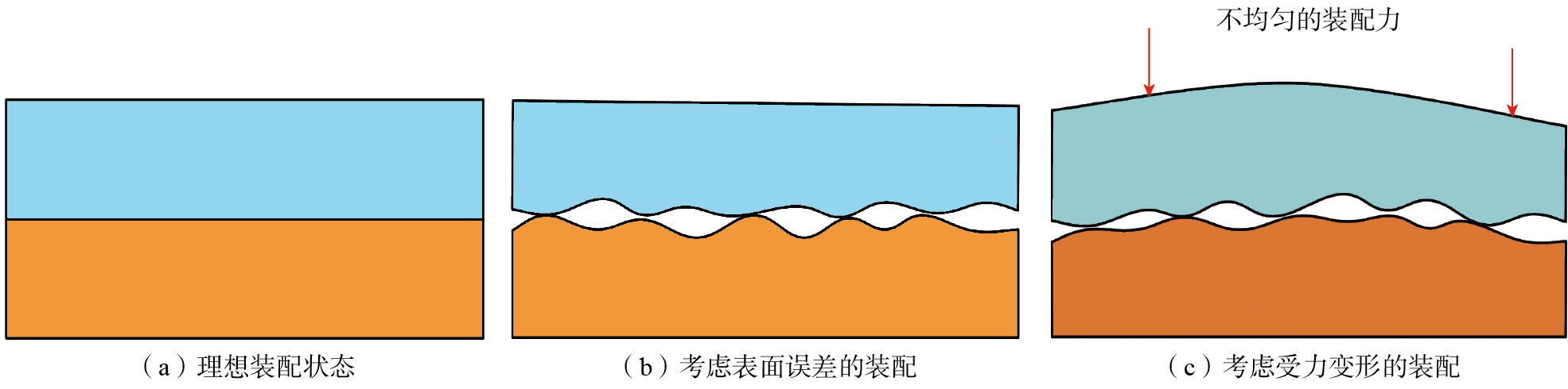
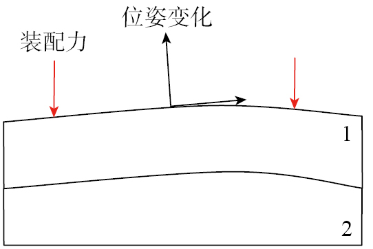
图1 不同装配状态示意图
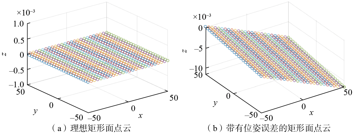
图2 不同表面的点云图
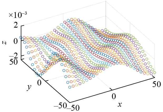
图3 带有形状误差的矩形面点云
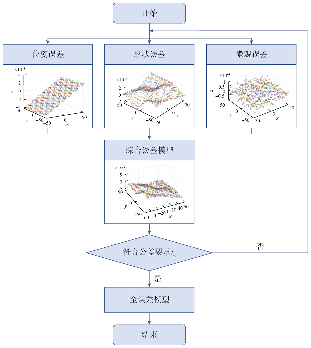
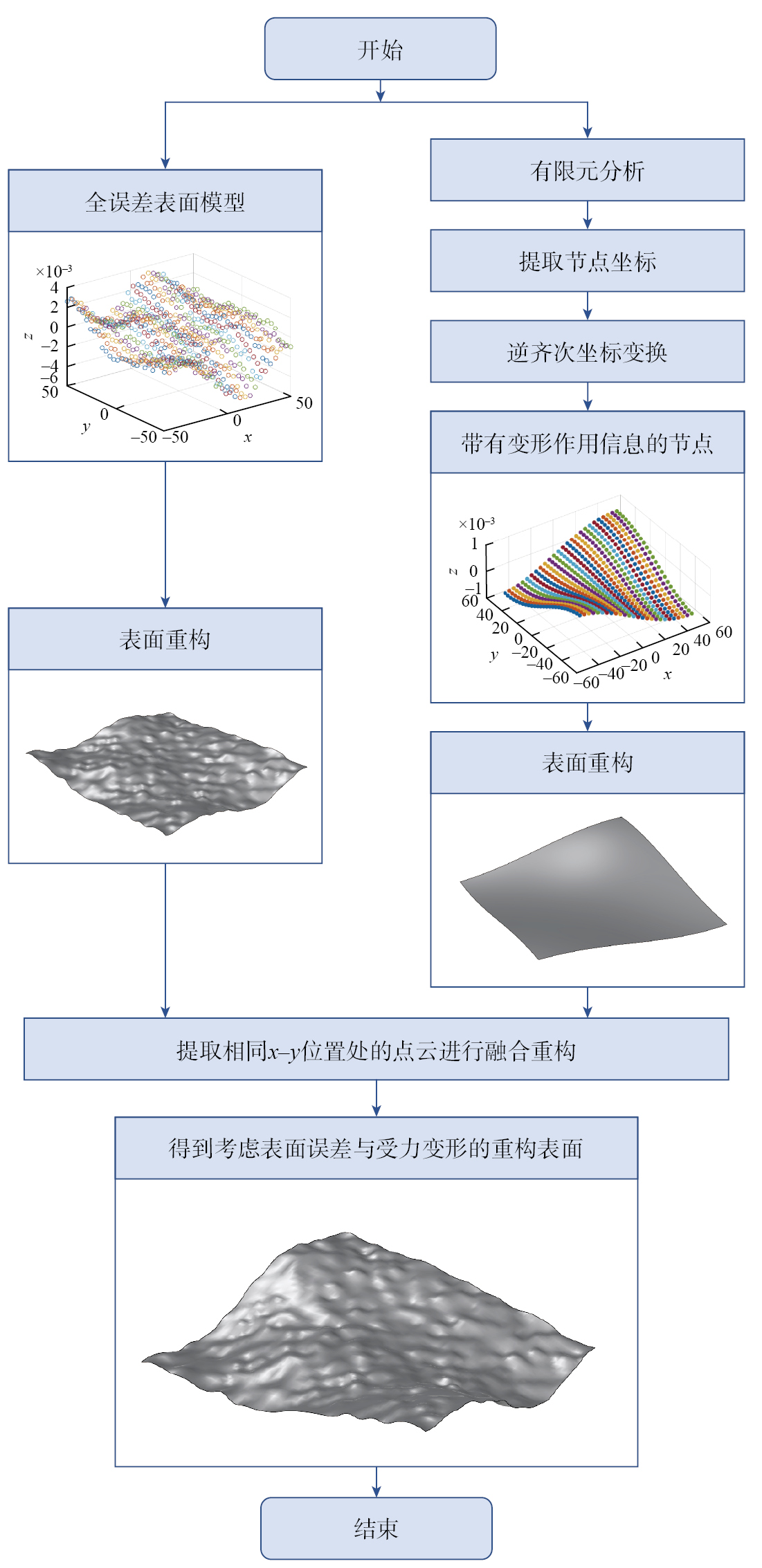
图4 几何全误差模型生成流程图
图5 零件受力变形产生的影响
图6 表面重构与融合流程图
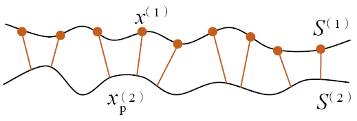
图7 表面离散化与最近点检测
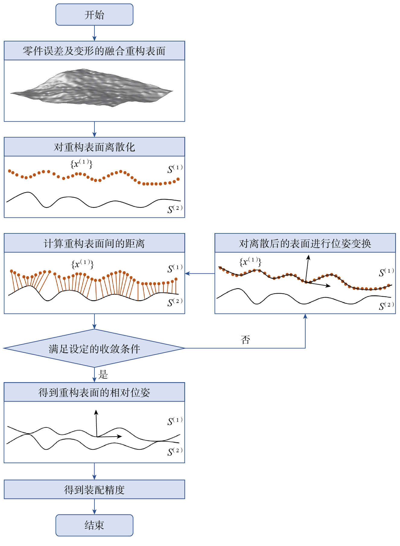
图8 装配精度计算流程图
图9 装配案例示意图
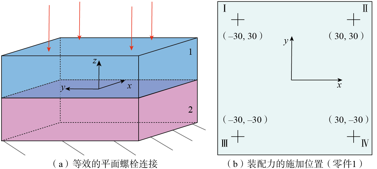
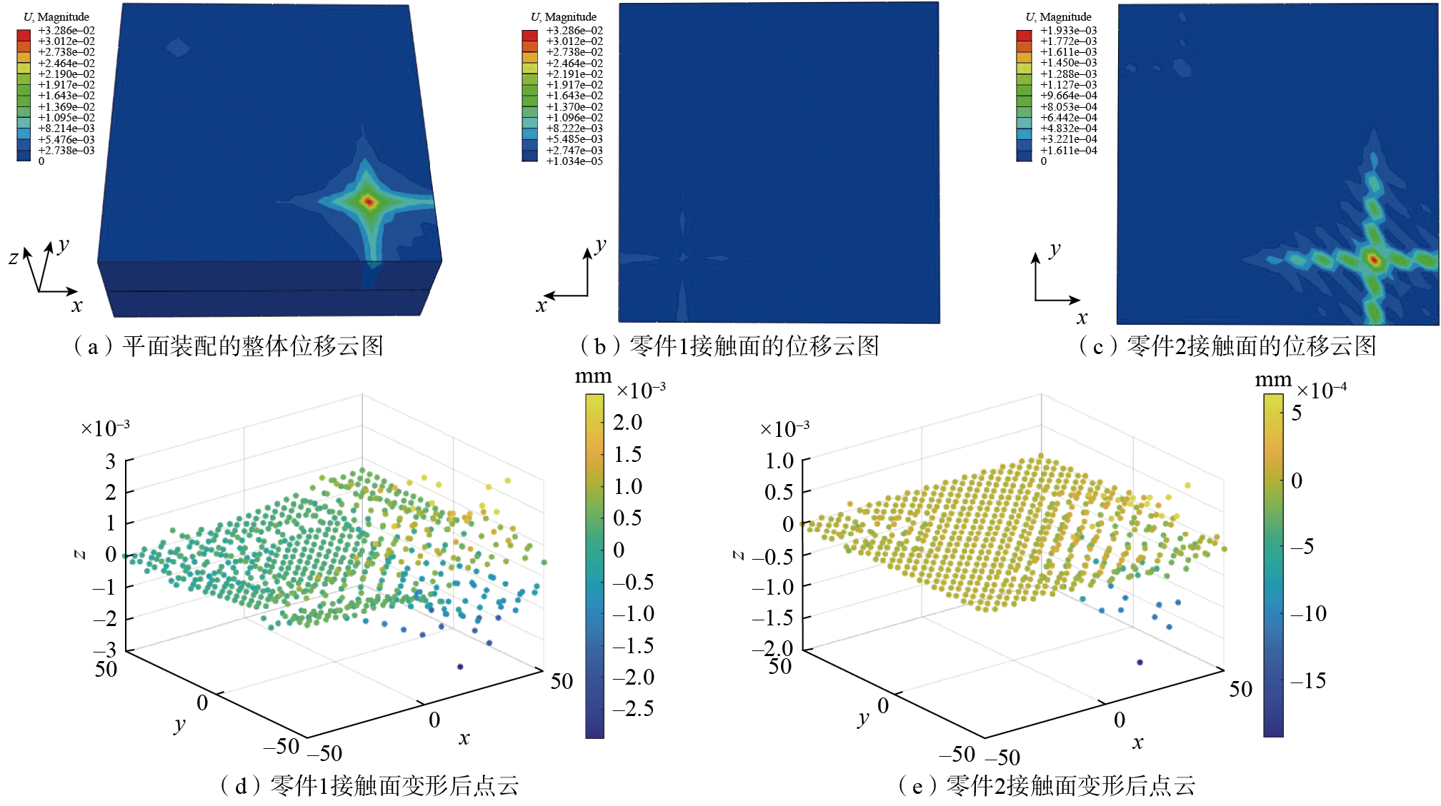
图10 平面螺栓连接的变形分析
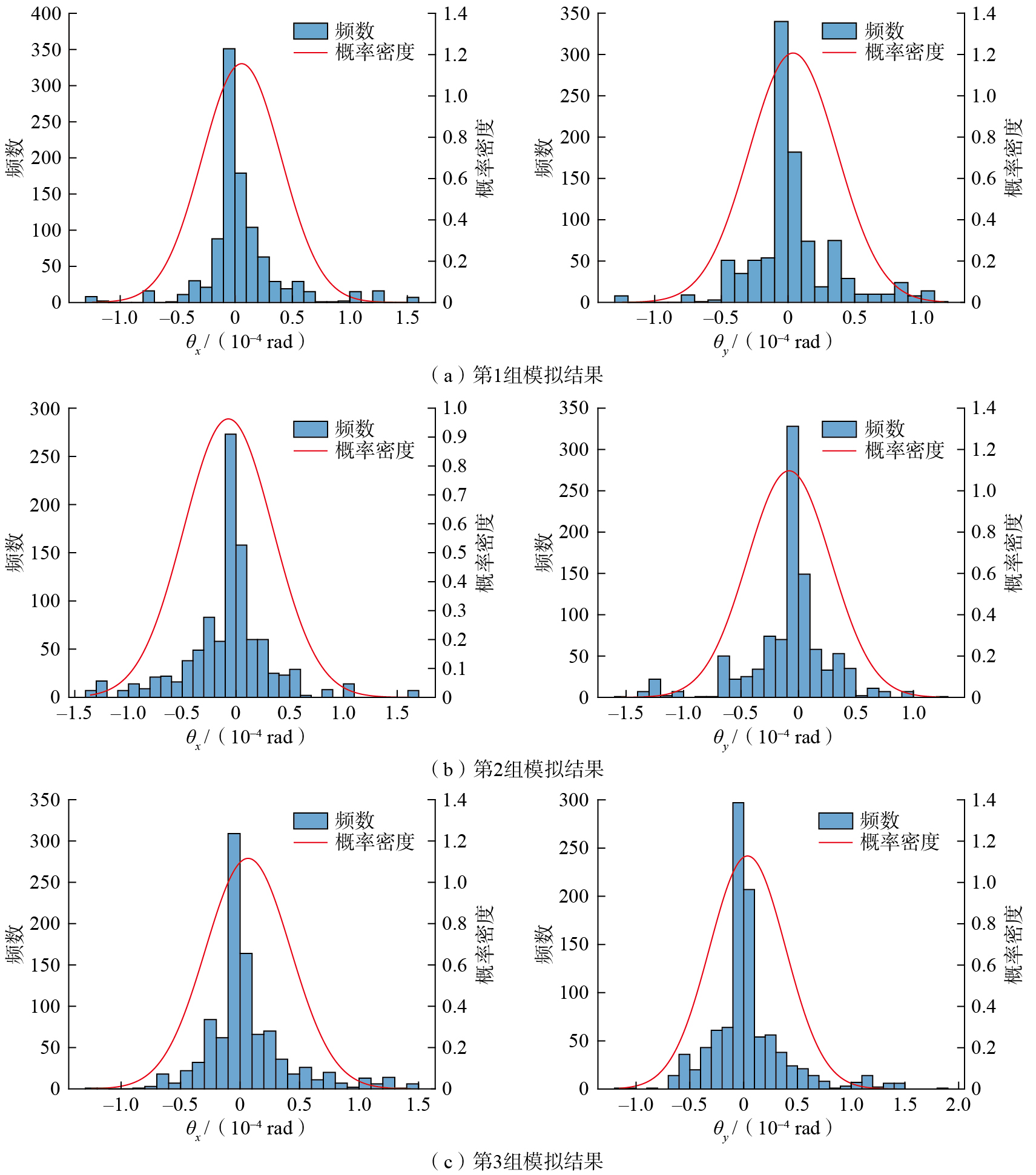
图11 平面螺栓连接的仿真模拟结果
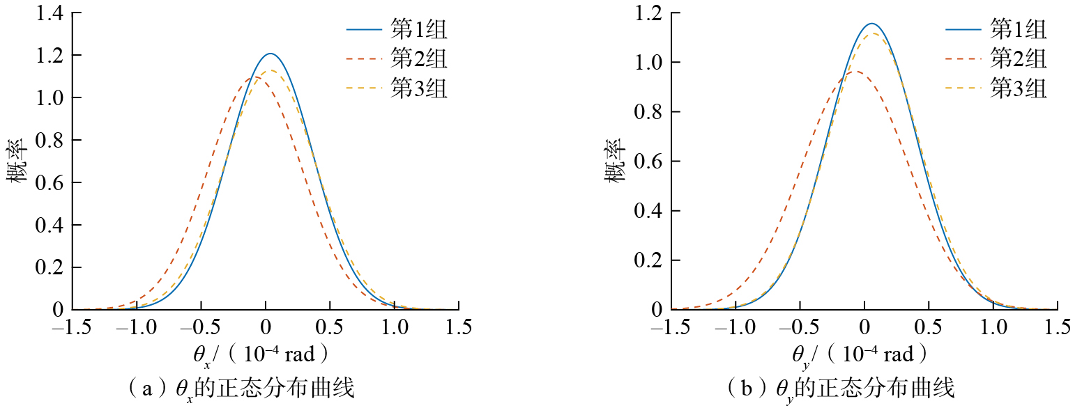
图12 不同平面螺栓连接的正态分布曲线
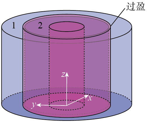
图13 柱面的过盈配合示意图
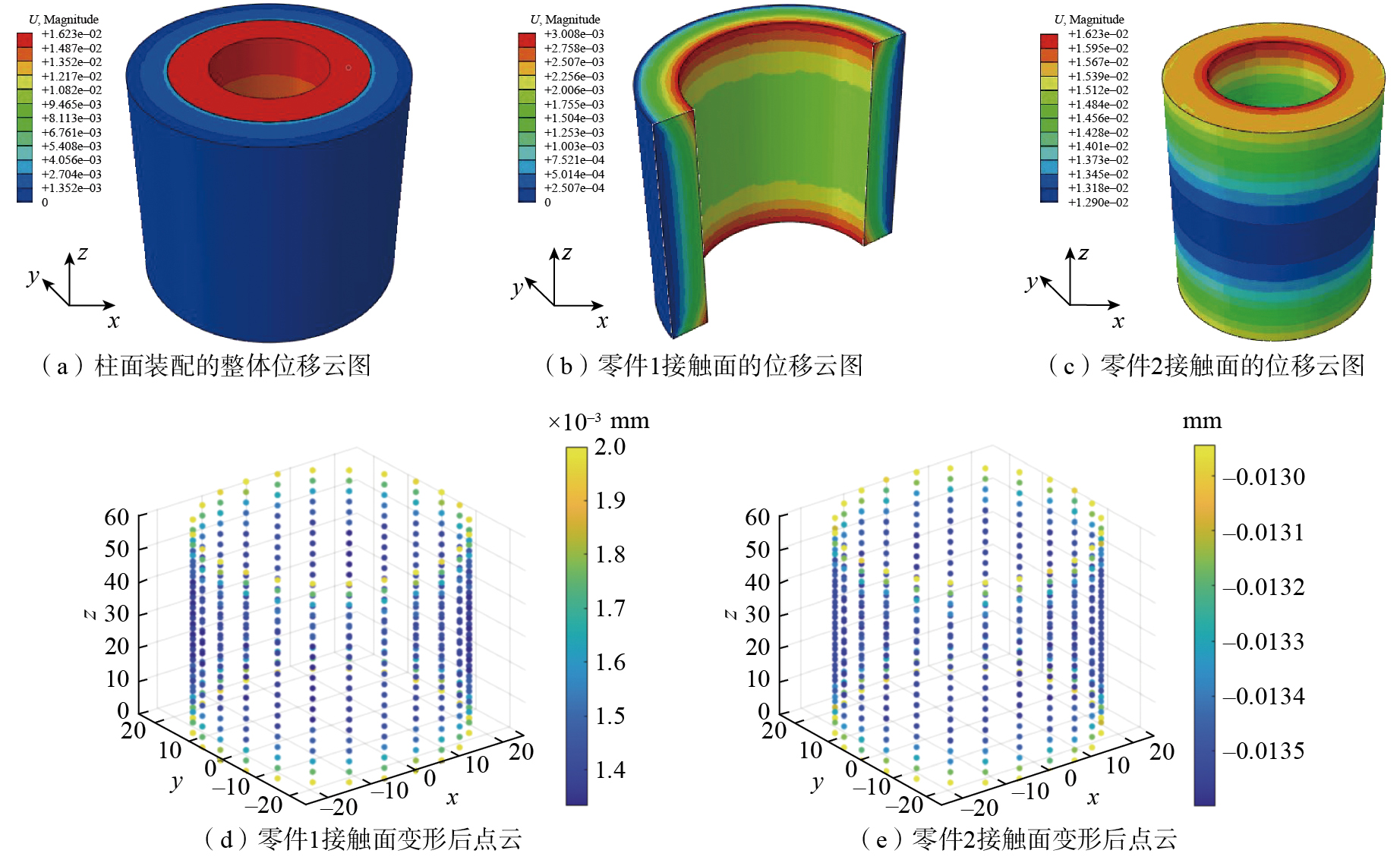
图14 柱面过盈配合的变形分析
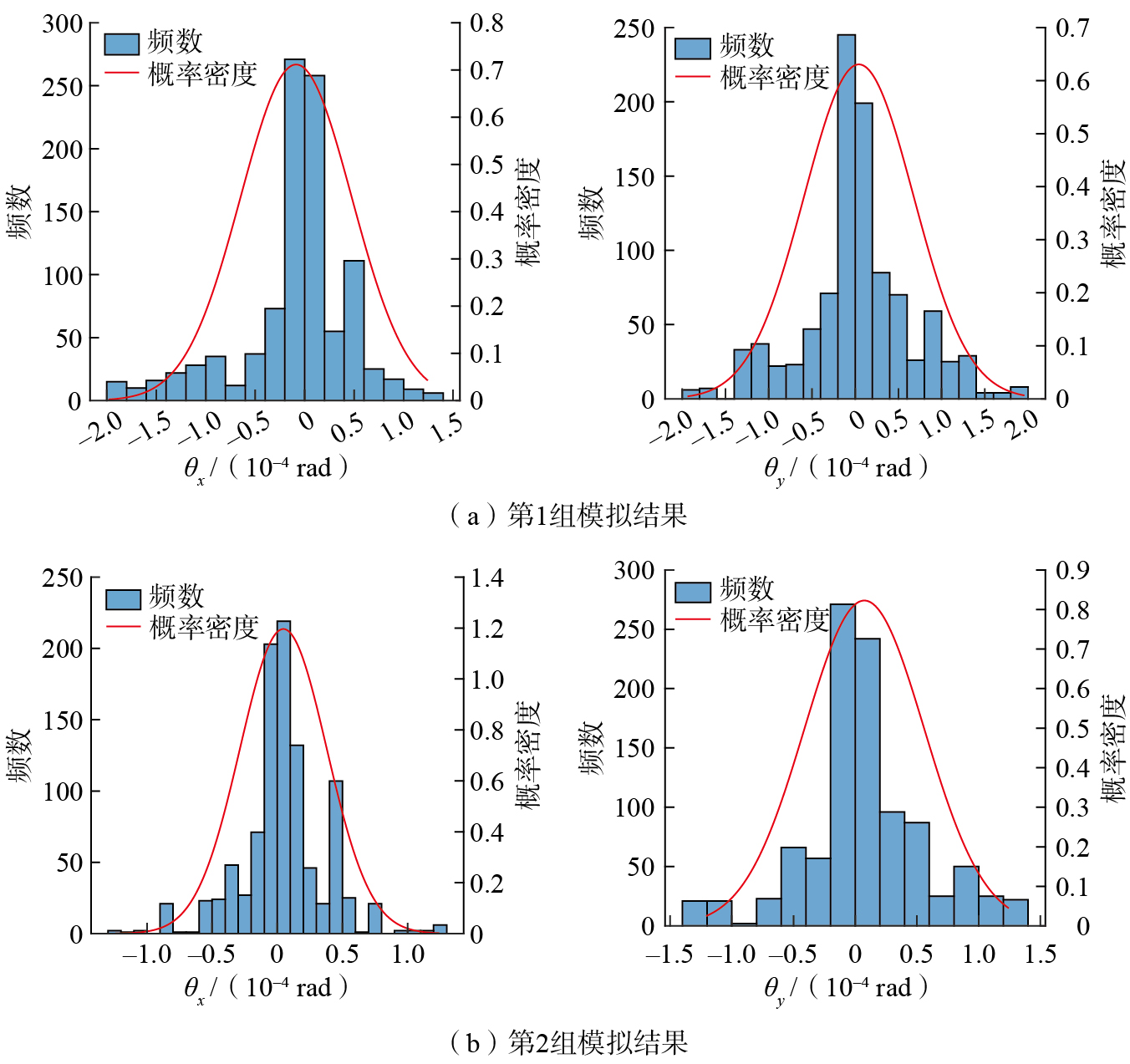
图15 柱面过盈配合的仿真模拟结果
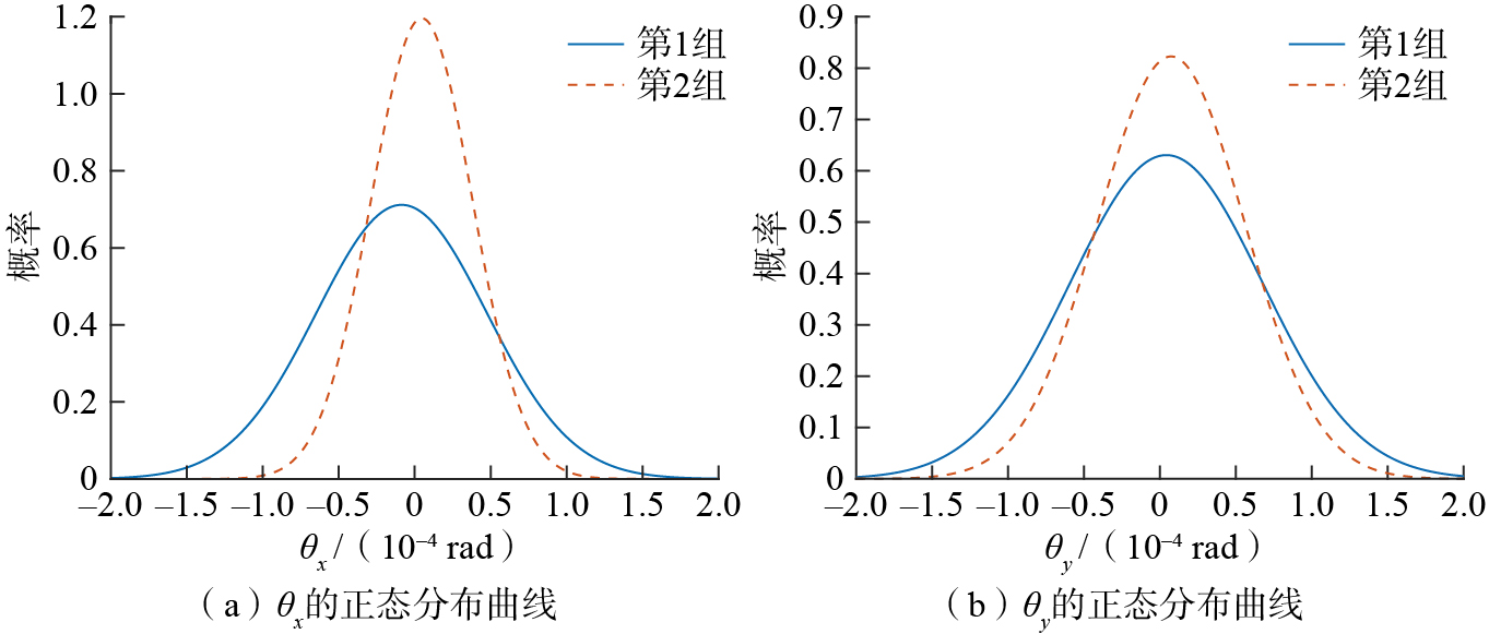
图16 不同柱面过盈配合的正态分布曲线
表1 定向及定位公差建模[ HUANG W Z, CEGLAREK D. Mode-based decomposition of part form error by discrete-cosine-transform with implementation to assembly and stamping system with compliant parts[J]. CIRP Annals, 2002, 51(1): 21–26. 17]
School of Mechanical Engineering, Xi’an Jiaotong University, Xi’an710049, China
Citations
YANG Yitao, ZHAO Qiangqiang, HU Xiaokun, et al. Research on assembly accuracy analysis integrating surface profile errors of part and force-induced deformations[J]. Aeronautical Manufacturing Technology, 2025, 68(18): 120–132.
Abstract
Assembly accuracy is crucial to the working performance of precision machinery, which is affected by the surface profile errors of parts in the manufacturing process and deformation under the action of assembly force. Hence, this study proposes an assembly accuracy analysis method that integrates the surface profile error of parts and deformation under force. Firstly, a small-displacement torsor model is used to model the pose error and a shape error model is constructed by combining the basis function superposition method, and a comprehensive surface error model is established by introducing a Gaussian function to generate random noise. Subsequently, a finite element method is used to analyze deformation of parts under force conditions and its influence on assembly pose, and non-uniform rational B-splines (NURBS) are used to fuse and reconstruct the surface shape and part deformation, generating a surface model of the part that simultaneously considers the surface profile error and force deformation. Finally, based on this model, the fit state between surfaces is evaluated by combining the nearest projected point method, and the assembly accuracy is then calculated by an optimization algorithm. The results of 1000 simulation experiments on planar bolted joints and interference fits of column surface show that different assembly forces or overloads affect the final assembly accuracy; the proposed method is able to carry out effective evaluation and provide guidance for actual assembly.
随着航空航天装备、精密机床和高精度测试设备的迅速发展,对装配精度的要求不断提高。高精度装配的核心在于对装配偏差的准确预测,而装配偏差的主要来源是零部件在制造过程中不可避免的几何误差[ BOSCHETTO A, BOTTINI L. Design for manufacturing of surfaces to improve accuracy in Fused Deposition Modeling[J]. Robotics and Computer-Integrated Manufacturing, 2016, 37: 103–114. 1]。这些误差导致了非理想的配合界面,直接影响装配精度。此外,在装配过程中,装配力作用下的零件变形也不可忽视,变形引发的进一步偏差使装配精度问题变得更加复杂。尤其是在高精度机械系统中,即使是微小的误差和变形都会累积,最终影响系统的功能和性能。因此,为了满足高精度装配要求,研究如何精确表征配合界面形态、准确预测装配偏差、综合考虑制造误差和装配力变形的影响,已成为当前高端制造领域的重要课题。
自20世纪中叶至今,研究人员提出了多种用于装配精度分析的理论模型,例如雅可比矩阵(Jacobian)模型[ LAPERRIÈRE L, ELMARAGHY H A. Tolerance analysis and synthesis using Jacobian transforms[J]. CIRP Annals, 2000, 49(1): 359–362. XI Y, GAO Z Y, CHEN K, et al. Error propagation model using Jacobian-torsor model weighting for assembly quality analysis on complex product[J]. Mathematics, 2022, 10(19): 3534. 2-3]、小位移旋量(Small displacement torsor,SDT)模型[ BOURDET P, CLEMENT A. A study of optimal-criteria identification based on the small-displacement screw model[J]. CIRP Annals, 1988, 37(1): 503–506. GUO J K, HONG J, YANG Z H, et al. A tolerance analysis method for rotating machinery[J]. Procedia CIRP, 2013, 10: 77–83. LI H, ZHU H P, LI P G, et al. Tolerance analysis of mechanical assemblies based on small displacement torsor and deviation propagation theories[J]. The International Journal of Advanced Manufacturing Technology, 2014, 72(1): 89–99. 4-6]及统一的雅可比–旋量(Unified Jacobian–torsor)模型[ DESROCHERS A, GHIE W, LAPERRIE`RE L. Application of a unified Jacobian-torsor model for tolerance analysis[J]. Journal of Computing and Information Science in Engineering, 2003, 3(1): 2–14. LAPERRIÈRE L, GHIE W, DESROCHERS A. Statistical and deterministic tolerance analysis and synthesis using a unified Jacobian-torsor model[J]. CIRP Annals, 2002, 51(1): 417–420. 7-8],这些模型被广泛应用于装配精度的分析中。Mu等[ MU X K, YUAN B, WANG Y L, et al. Novel application of mapping method from small displacement torsor to tolerance: Error optimization design of assembly parts[J]. Proceedings of the Institution of Mechanical Engineers, Part B: Journal of Engineering Manufacture, 2022, 236(6–7): 955–967. 9]基于SDT模型对航空发动机高压转子进行了装配误差优化设计;Aoufi等[ AOUFI B, AMEDDAH H, SLAMANI M, et al. An advanced framework for tolerance analysis of cam-clamping devices integrating unified Jacobian-torsor model, Monte Carlo simulation, and bootstrap technique[J]. The International Journal of Advanced Manufacturing Technology, 2024, 134(5): 2319–2336. 10]则利用统一的雅可比–旋量模型对凸轮夹紧装置进行了公差分析;Gouyou等[ GOUYOU D, TEISSANDIER D, DELOS V, et al. Statistical tolerance analysis applied on overconstrained mechanisms with form deviations[J]. Journal of Computational Design and Engineering, 2020, 7(3): 308–322. 11]使用多面体模型对过约束法兰进行了公差分析。然而,随着精密机械装配技术的发展,研究人员逐渐认识到,配合面的真实形貌对装配精度有着不可忽视的影响[ SHAO N, DING X Y, LIU J H. Tolerance analysis of spur gears based on skin model shapes and a boundary element method[J]. Mechanism and Machine Theory, 2020, 144: 103658. 12]。传统基于SDT的方法虽然能够将表面误差纳入装配分析,但往往将表面误差简化为特征面的平移和旋转[ HU X K, ZHAO Q Q, YANG Y T, et al. Accuracy analysis for machine tool spindles considering full parallel connections and form errors based on skin model shapes[J]. Journal of Computational Design and Engineering, 2023, 10(5): 1970–1987. 13],无法准确反映真实的表面形貌。为了更精确地描述表面形貌,研究人员发展了多种建模方法来表征复杂的几何误差[ YAN X, BALLU A. Review and comparison of form error simulation methods for computer-aided tolerancing[J]. Journal of Computing and Information Science in Engineering, 2019, 19(1): 010802. SCHLEICH B, WARTZACK S. Approaches for the assembly simulation of skin model shapes[J]. Computer-Aided Design, 2015, 65: 18–33. MA S H, HU T L, XIONG Z Q. Precision assembly simulation of skin model shapes accounting for contact deformation and geometric deviations for statistical tolerance analysis method[J]. International Journal of Precision Engineering and Manufacturing, 2021, 22(6): 975–989. 14-16]。例如,Huang等[ HUANG W Z, CEGLAREK D. Mode-based decomposition of part form error by discrete-cosine-transform with implementation to assembly and stamping system with compliant parts[J]. CIRP Annals, 2002, 51(1): 21–26. 17]提出了一种基于离散余弦变换(Discrete cosine transformation,DCT)的表面误差分解与表征方法,可有效捕捉表面细节特征;Zhang等[ ZHANG Z Q, ZHANG Z J, JIN X, et al. A novel modelling method of geometric errors for precision assembly[J]. The International Journal of Advanced Manufacturing Technology, 2018, 94(1): 1139–1160. 18]采用非均匀有理B样条(NURBS)表示几何误差,构建了高精度的几何实体模型;Otsuka等[ OTSUKA A, MIYAZAKI S, SUZUKI S, et al. Parameter optimization for random generation of non-ideal surfaces using dual-tree complex wavelet transform[J]. Procedia CIRP, 2024, 129: 246–251. 19]利用小波变换生成了非理想曲面。结合表面形貌的装配精度分析同样得到了广泛研究,Samper等[ SAMPER S, ADRAGNA P A, FAVRELIERE H, et al. Modeling of 2D and 3D assemblies taking into account form errors of plane surfaces[J]. Journal of Computing and Information Science in Engineering, 2009, 9(4): 041005. 20]使用模态分解方法描述形状误差,并与SDT模型结合进行装配精度分析;Sun等[ SUN Q C, ZHAO B B, LIU X, et al. Assembling deviation estimation based on the real mating status of assembly[J]. Computer-Aided Design, 2019, 115: 244–255. 21]通过小波变换分解和重建配合表面形态,同时集成SDT模型来计算装配偏差;Yang[ YANG Y, LIU X, LIU T, et al. A generic integrated approach of assembly tolerance analysis based on skin model shapes[J]. Proceedings of the Institution of Mechanical Engineers, Part B: Journal of Engineering Manufacture, 2021, 235(4): 689–704. 22]和Yi[ YI Y, LIU T Y, YAN Y H, et al. A novel assembly tolerance analysis method considering form errors and partial parallel connections[J]. The International Journal of Advanced Manufacturing Technology, 2024, 131(11): 5489–5510. 23]等利用肤面模型对非理想曲面进行建模,将几何偏差纳入公差分析框架中,为装配分析提供了更加真实的几何描述。
此外,零件的柔性特性使零件在装配过程中不可避免地发生变形,导致装配精度的分析变得更加复杂,这种变形不仅影响接触面的形状,还可能引发装配体姿态的整体偏移。近年来,学者们在装配精度分析中逐渐引入了零件变形的计算,以提升装配精度分析模型的分析效果[ CAI N, QIAO L, ANWER N. Unified variation modeling of sheet metal assembly considering rigid and compliant variations[J]. Proceedings of the Institution of Mechanical Engineers, Part B: Journal of Engineering Manufacture, 2015, 229(3): 495–507. ZHI J N, CAO Y L, LIU F, et al. Tolerance analysis of an assembly by considering part deformation[J]. Procedia CIRP, 2020, 92: 81–87. 24-25]。例如,Wang等[ WANG K, LIU D X, LIU Z Y, et al. An assembly precision analysis method based on a general part digital twin model[J]. Robotics and Computer-Integrated Manufacturing, 2021, 68: 102089. 26]通过有限元法计算配合面的变形,并将变形量叠加到装配精度分析模型中,从而更准确地评估装配体的偏差;Liu等[ LIU T, ZHU Z W, CAO Y L, et al. Consideration of working conditions in assembly tolerance analysis[J]. Procedia CIRP, 2018, 75: 226–231. LIU T, CAO Y L, WANG J, et al. Assembly error calculation with consideration of part deformation[J]. Procedia CIRP, 2016, 43: 58–63. 27-28]结合雅可比–旋量模型,将有限元计算变形引起的偏差纳入统一框架,以支持复杂装配环境下的公差分析;Guo等[ GUO J K, LI B T, LIU Z G, et al. Integration of geometric variation and part deformation into variation propagation of 3-D assemblies[J]. International Journal of Production Research, 2016, 54(19): 5708–5721. 29]则提出了一种弹性配合面的线性等效模型,利用弹簧特性表征接触变形,显著降低了计算复杂度;Grandjean等[ GRANDJEAN J, LEDOUX Y, SAMPER S. On the role of form defects in assemblies subject to local deformations and mechanical loads[J]. The International Journal of Advanced Manufacturing Technology, 2013, 65(9): 1769–1778. 30]通过模拟材料的纯塑性行为研究了局部表面变形对环形配合表面的影响,揭示了形状误差对装配精度的影响。此外,Liu等[ LIU J H, ZHANG Z Q, DING X Y, et al. Integrating form errors and local surface deformations into tolerance analysis based on skin model shapes and a boundary element method[J]. Computer-Aided Design, 2018, 104: 45–59. 31]采用肤面形状模型表示表面误差,并结合边界元法(BEM)解决误差表面之间的接触问题;Sa等[ SA G D, BAI H D, LIU Z Y, et al. A tolerance analysis method based on assembly deformation simulation with stable contact[J]. Robotic Intelligence and Automation, 2024, 44(1): 1–18. 32]利用BEM计算局部变形,并结合SDT进行公差分析。这些研究在一定程度上同时考虑了表面形貌和零件变形,但多数方法还不能达到完美融合;而且部分方法受限于特定几何形状,在建模过程中损失了表面细节特征。
位姿误差包括定位误差与定向误差。假定在定位公差和定向公差的约束下,几何特征的定位误差和定向误差可以用小位移旋量来表示。几何特征的偏离通常分为平移矢量ρ=(u v w)T和旋转矢量ε=(α β γ)T,分别描述了几何特征在位置上的移动和在方向上的偏转,可以通过齐次坐标变换矩阵的形式使得这两组矢量的描述和运算更简洁。在齐次坐标中,平移矢量作为位移分量,而旋转矢量通过矩阵变换体现,最终通过齐次坐标变换矩阵T对几何偏差进行统一描述,即
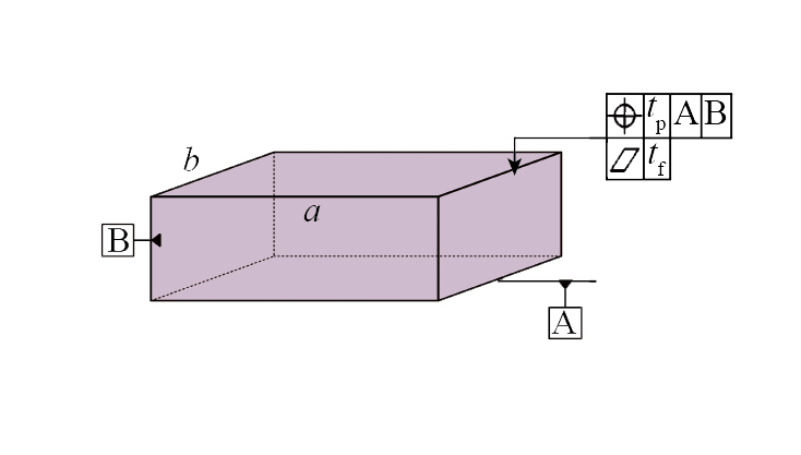
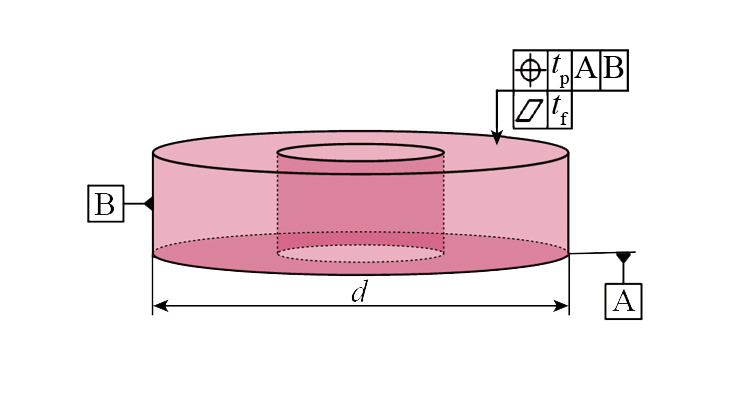
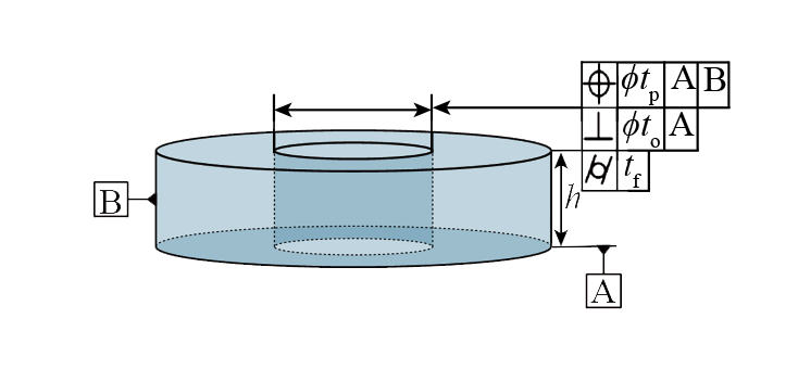
表1 定向及定位公差建模[ HUANG W Z, CEGLAREK D. Mode-based decomposition of part form error by discrete-cosine-transform with implementation to assembly and stamping system with compliant parts[J]. CIRP Annals, 2002, 51(1): 21–26. 17]
Table 1 Modeling for orientation and positioning tolerance[ HUANG W Z, CEGLAREK D. Mode-based decomposition of part form error by discrete-cosine-transform with implementation to assembly and stamping system with compliant parts[J]. CIRP Annals, 2002, 51(1): 21–26. 17]
式中,Pij为控制点;ωij为与控制点对应的权重;p、q为基函数的次数;N′为基函数,可通过Cox-de Boor公式得到[ PIEGL L, TILLER W. The NURBS Book[M]. Cham: Springer Berlin Heidelberg, 1997. KHALAFI V, FAZILATI J. Panel flutter analysis of cracked functionally graded plates in yawed supersonic flow with thermal effects[J]. Applied Mathematical Modelling, 2022, 101: 259–275. QIN X C, DONG C Y, WANG F, et al. Static and dynamic analyses of isogeometric curvilinearly stiffened plates[J]. Applied Mathematical Modelling, 2017, 45: 336–364. YIN S H, DENG Y, YU T T, et al. Isogeometric analysis for non-classical Bernoulli-Euler beam model incorporating microstructure and surface energy effects[J]. Applied Mathematical Modelling, 2021, 89: 470–485. 33-36],即
BOSCHETTOA, BOTTINIL. Design for manufacturing of surfaces to improve accuracy in Fused Deposition Modeling[J]. Robotics and Computer-Integrated Manufacturing, 2016, 37: 103–114.
[2]
LAPERRIÈREL, ELMARAGHYH A. Tolerance analysis and synthesis using Jacobian transforms[J]. CIRP Annals, 2000, 49(1): 359–362.
[3]
XIY, GAOZ Y, CHENK, et al. Error propagation model using Jacobian-torsor model weighting for assembly quality analysis on complex product[J]. Mathematics, 2022, 10(19): 3534.
[4]
BOURDETP, CLEMENTA. A study of optimal-criteria identification based on the small-displacement screw model[J]. CIRP Annals, 1988, 37(1): 503–506.
[5]
GUOJ K, HONGJ, YANGZ H, et al. A tolerance analysis method for rotating machinery[J]. Procedia CIRP, 2013, 10: 77–83.
[6]
LIH, ZHUH P, LIP G, et al. Tolerance analysis of mechanical assemblies based on small displacement torsor and deviation propagation theories[J]. The International Journal of Advanced Manufacturing Technology, 2014, 72(1): 89–99.
[7]
DESROCHERSA, GHIEW, LAPERRIE`REL. Application of a unified Jacobian-torsor model for tolerance analysis[J]. Journal of Computing and Information Science in Engineering, 2003, 3(1): 2–14.
[8]
LAPERRIÈREL, GHIEW, DESROCHERSA. Statistical and deterministic tolerance analysis and synthesis using a unified Jacobian-torsor model[J]. CIRP Annals, 2002, 51(1): 417–420.
[9]
MUX K, YUANB, WANGY L, et al. Novel application of mapping method from small displacement torsor to tolerance: Error optimization design of assembly parts[J]. Proceedings of the Institution of Mechanical Engineers, Part B: Journal of Engineering Manufacture, 2022, 236(6–7): 955–967.
[10]
AOUFIB, AMEDDAHH, SLAMANIM, et al. An advanced framework for tolerance analysis of cam-clamping devices integrating unified Jacobian-torsor model, Monte Carlo simulation, and bootstrap technique[J]. The International Journal of Advanced Manufacturing Technology, 2024, 134(5): 2319–2336.
[11]
GOUYOUD, TEISSANDIERD, DELOSV, et al. Statistical tolerance analysis applied on overconstrained mechanisms with form deviations[J]. Journal of Computational Design and Engineering, 2020, 7(3): 308–322.
[12]
SHAON, DINGX Y, LIUJ H. Tolerance analysis of spur gears based on skin model shapes and a boundary element method[J]. Mechanism and Machine Theory, 2020, 144: 103658.
[13]
HUX K, ZHAOQ Q, YANGY T, et al. Accuracy analysis for machine tool spindles considering full parallel connections and form errors based on skin model shapes[J]. Journal of Computational Design and Engineering, 2023, 10(5): 1970–1987.
[14]
YANX, BALLUA. Review and comparison of form error simulation methods for computer-aided tolerancing[J]. Journal of Computing and Information Science in Engineering, 2019, 19(1): 010802.
[15]
SCHLEICHB, WARTZACKS. Approaches for the assembly simulation of skin model shapes[J]. Computer-Aided Design, 2015, 65: 18–33.
[16]
MAS H, HUT L, XIONGZ Q. Precision assembly simulation of skin model shapes accounting for contact deformation and geometric deviations for statistical tolerance analysis method[J]. International Journal of Precision Engineering and Manufacturing, 2021, 22(6): 975–989.
[17]
HUANGW Z, CEGLAREKD. Mode-based decomposition of part form error by discrete-cosine-transform with implementation to assembly and stamping system with compliant parts[J]. CIRP Annals, 2002, 51(1): 21–26.
[18]
ZHANGZ Q, ZHANGZ J, JINX, et al. A novel modelling method of geometric errors for precision assembly[J]. The International Journal of Advanced Manufacturing Technology, 2018, 94(1): 1139–1160.
[19]
OTSUKAA, MIYAZAKIS, SUZUKIS, et al. Parameter optimization for random generation of non-ideal surfaces using dual-tree complex wavelet transform[J]. Procedia CIRP, 2024, 129: 246–251.
[20]
SAMPERS, ADRAGNAP A, FAVRELIEREH, et al. Modeling of 2D and 3D assemblies taking into account form errors of plane surfaces[J]. Journal of Computing and Information Science in Engineering, 2009, 9(4): 041005.
[21]
SUNQ C, ZHAOB B, LIUX, et al. Assembling deviation estimation based on the real mating status of assembly[J]. Computer-Aided Design, 2019, 115: 244–255.
[22]
YANGY, LIUX, LIUT, et al. A generic integrated approach of assembly tolerance analysis based on skin model shapes[J]. Proceedings of the Institution of Mechanical Engineers, Part B: Journal of Engineering Manufacture, 2021, 235(4): 689–704.
[23]
YIY, LIUT Y, YANY H, et al. A novel assembly tolerance analysis method considering form errors and partial parallel connections[J]. The International Journal of Advanced Manufacturing Technology, 2024, 131(11): 5489–5510.
[24]
CAIN, QIAOL, ANWERN. Unified variation modeling of sheet metal assembly considering rigid and compliant variations[J]. Proceedings of the Institution of Mechanical Engineers, Part B: Journal of Engineering Manufacture, 2015, 229(3): 495–507.
[25]
ZHIJ N, CAOY L, LIUF, et al. Tolerance analysis of an assembly by considering part deformation[J]. Procedia CIRP, 2020, 92: 81–87.
[26]
WANGK, LIUD X, LIUZ Y, et al. An assembly precision analysis method based on a general part digital twin model[J]. Robotics and Computer-Integrated Manufacturing, 2021, 68: 102089.
[27]
LIUT, ZHUZ W, CAOY L, et al. Consideration of working conditions in assembly tolerance analysis[J]. Procedia CIRP, 2018, 75: 226–231.
[28]
LIUT, CAOY L, WANGJ, et al. Assembly error calculation with consideration of part deformation[J]. Procedia CIRP, 2016, 43: 58–63.
[29]
GUOJ K, LIB T, LIUZ G, et al. Integration of geometric variation and part deformation into variation propagation of 3-D assemblies[J]. International Journal of Production Research, 2016, 54(19): 5708–5721.
[30]
GRANDJEANJ, LEDOUXY, SAMPERS. On the role of form defects in assemblies subject to local deformations and mechanical loads[J]. The International Journal of Advanced Manufacturing Technology, 2013, 65(9): 1769–1778.
[31]
LIUJ H, ZHANGZ Q, DINGX Y, et al. Integrating form errors and local surface deformations into tolerance analysis based on skin model shapes and a boundary element method[J]. Computer-Aided Design, 2018, 104: 45–59.
[32]
SAG D, BAIH D, LIUZ Y, et al. A tolerance analysis method based on assembly deformation simulation with stable contact[J]. Robotic Intelligence and Automation, 2024, 44(1): 1–18.
[33]
PIEGLL, TILLERW. The NURBS Book[M]. Cham: Springer Berlin Heidelberg, 1997.
[34]
KHALAFIV, FAZILATIJ. Panel flutter analysis of cracked functionally graded plates in yawed supersonic flow with thermal effects[J]. Applied Mathematical Modelling, 2022, 101: 259–275.
[35]
QINX C, DONGC Y, WANGF, et al. Static and dynamic analyses of isogeometric curvilinearly stiffened plates[J]. Applied Mathematical Modelling, 2017, 45: 336–364.
[36]
YINS H, DENGY, YUT T, et al. Isogeometric analysis for non-classical Bernoulli-Euler beam model incorporating microstructure and surface energy effects[J]. Applied Mathematical Modelling, 2021, 89: 470–485.