Influence of Interface Morphology on Residual Stress Distribution of Self-Healing Thermal Barrier Coatings
Citations
ZHAO Weiling, WANG Liang. Influence of interface morphology on residual stress distribution of self-healing thermal barrier coatings[J]. Aeronautical Manufacturing Technology, 2025, 68(18): 62–73.
图1 大气等离子喷涂热障涂层自修复原理机制图[ WANG L, SHAO F, ZHONG X H, et al. Tailoring of self-healing thermal barrier coatings via finite element method[J]. Applied Surface Science, 2018, 431: 60–74. 29]
图2 自修复热障涂层的结构设计与自修复机理示意图
图3 自修复热障涂层显微照片
图4 自修复涂层理想余弦模型示意图
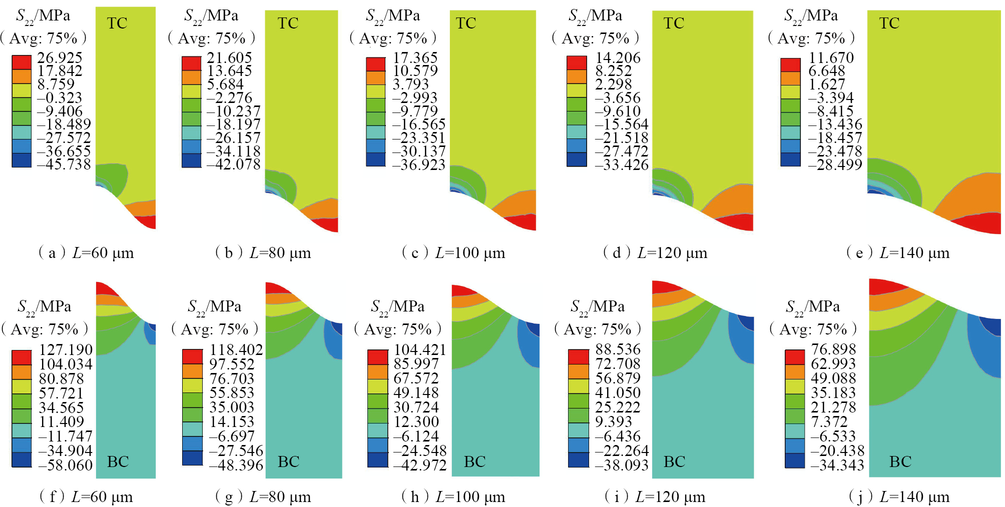
图5 不同波长下的S22应力分布云图
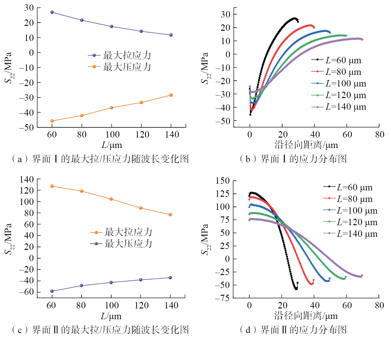
图6 不同波长下S22应力变化趋势
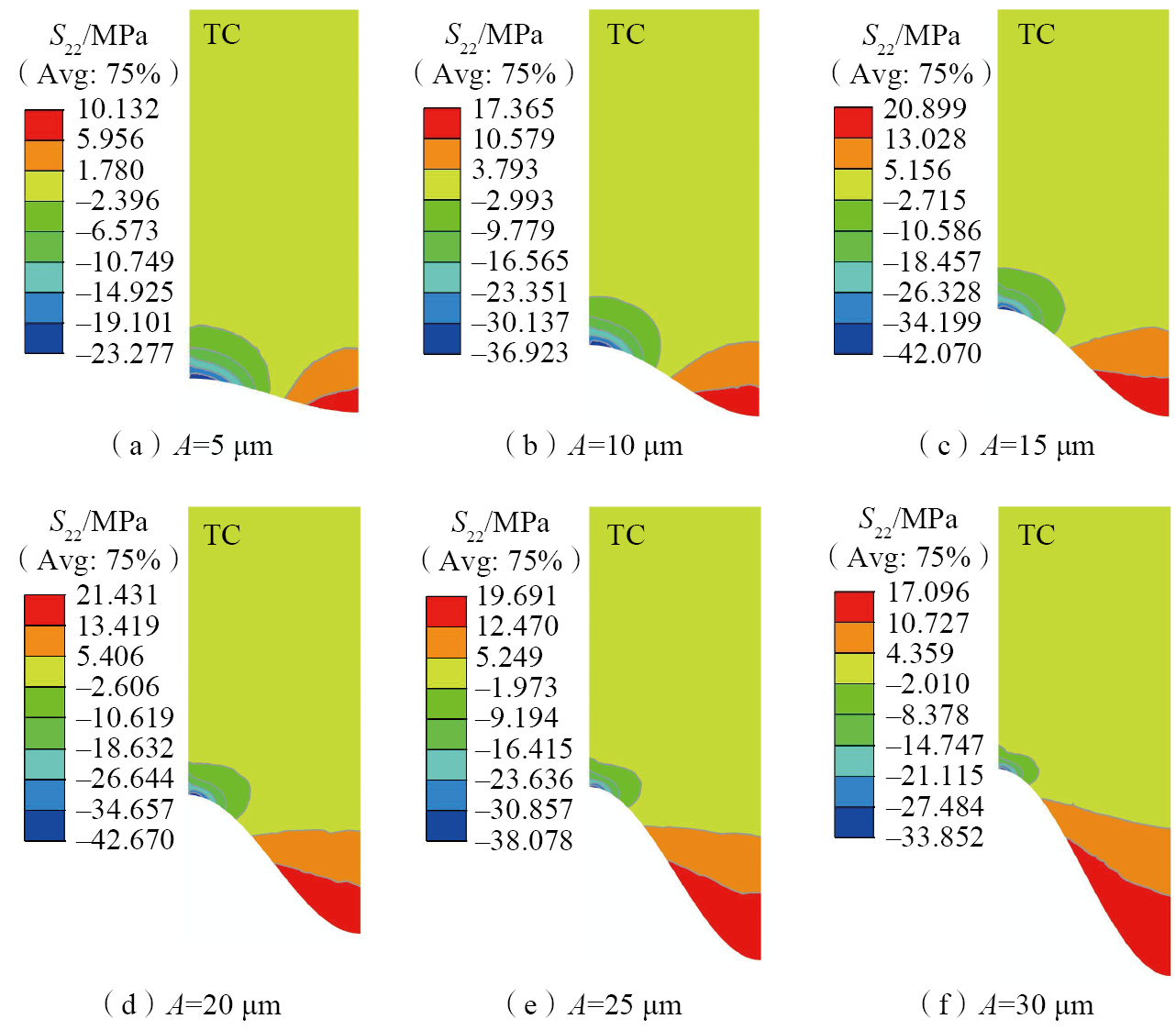
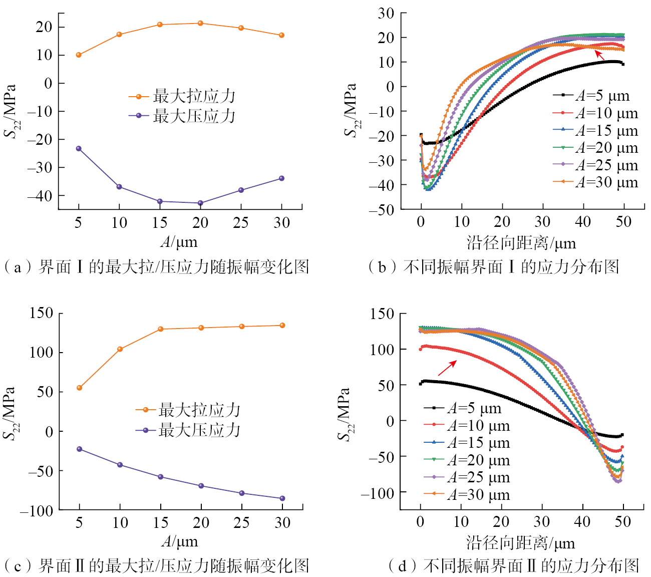
图7 不同振幅界面Ⅰ的S22应力分布云图
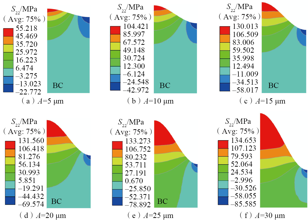
图8 不同振幅界面Ⅱ的S22应力分布云图
图9 不同振幅下S22应力变化趋势
图10 TAZ与TC界面幅值增加导致的界面应力变化解释示意图
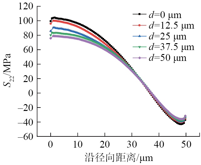
图11 界面Ⅱ的应力分布图
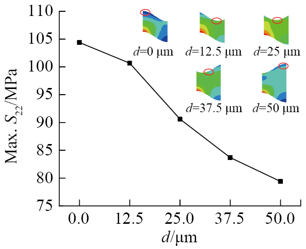
图12 界面Ⅱ的最大拉应力随d变化图
图13 TBCs在不同残余应力状态下的失效模式 [ ZHAO W L, HU Z C, WANG L, et al. Effect of top-coat thickness and interface fluctuation on the residual stress in APS–TBCs[J]. Coatings, 2023, 13(9): 1659. 38]
图14 真实喷涂态自修复热障涂层应力状态
表1 网格无关性计算结果
表2 8YSZ的材料参数[ OUYANG T Y, SUO J P. TiC-self-healing thermal barrier coating structures and oxidation resistance[J]. Surface and Coatings Technology, 2021, 412: 127065. 32]
表3 NiCoCrAlY的材料参数[ OUYANG T Y, SUO J P. TiC-self-healing thermal barrier coating structures and oxidation resistance[J]. Surface and Coatings Technology, 2021, 412: 127065. 32]
表4 高温合金基体的材料参数[ OUYANG T Y, SUO J P. TiC-self-healing thermal barrier coating structures and oxidation resistance[J]. Surface and Coatings Technology, 2021, 412: 127065. 32]
表5 TiC的物性参数[ ZHUANG M X, YUAN J H, HU Z C, et al. Design and optimization of coating structure for plasma sprayed self-healing MgO coating via finite element method[J]. Ceramics International, 2021, 47(2): 2414–2429. 43]
表6 Al2O3的物性参数[ HAN M, HUANG J H, CHEN S H. Behavior and mechanism of the stress buffer effect of the inside ceramic layer to the top ceramic layer in a double-ceramic-layer thermal barrier coating[J]. Ceramics International, 2014, 40(2): 2901–2914. 44]
1.State Key Laboratory of High Performance Ceramics, Shanghai Institute of Ceramics, Chinese Academy of Sciences, Shanghai201899, China
2.College of Materials Science and Optoelectronic Technology, University of Chinese Academy of Sciences, Beijing100049, China
Citations
ZHAO Weiling, WANG Liang. Influence of interface morphology on residual stress distribution of self-healing thermal barrier coatings[J]. Aeronautical Manufacturing Technology, 2025, 68(18): 62–73.
Abstract
During the coating preparation process, differences in the morphology, size, molten state, flight path, and spreading behavior on the substrate of the feedstock result in a certain degree of undulation within and among the adjacent coating layers. Changes in the geometry of the interface of the coatings make the morphology at the interface more complex, showing irregular and inhomogeneous structural characteristics. It also further makes the stress distribution at the interface uneven, leading to unpredictable failure of the self-healing TBCs at the interface in the subsequent service process, which in turn leads to the warpage or delamination failure of the entire coating. Finite element software was used to simulate the effect of the variation of the surface morphology on the residual stress which is inside the coating and at the interface. By establishing the cosine ideal interface model, it is found that when the wavelength L of interface Ⅰ and interface Ⅱ increases, both the maximum S22 tensile stress and compressive stress of interface Ⅰ and interface Ⅱ decrease. When the amplitude A of interfaces Ⅰ and Ⅱ increases, the stress is affected by both interface roughness and interface buffer stress. Varying the phase offset d between the peaks at the upper and lower interfaces, it is found that the microstructural characteristics of interface Ⅰ have a greater influence on the tensile stress at the peaks of interface Ⅱ. When the valley of interface I faces the peak of interface Ⅱ, this morphology pattern can reduce the maximum tensile stress of interface Ⅱ by 25.7% and avoid excessive stresses at interface Ⅱ. Further, the failure mechanism of the coating is systematically investigated, which provides a more comprehensive theoretical guidance for the optimal control of the interface of the self-healing thermal barrier coatings and the optimal design of the processing technology.
热障涂层(Thermal barrier coatings,TBCs)作为航空发动机及燃气轮机高温部件的核心热防护技术,通过金属–陶瓷多层结构设计实现了基体合金表面降温(100~300 ℃)[ THAKARE J G, PANDEY C, MAHAPATRA M M, et al. Thermal barrier coatings—A state of the art review[J]. Metals and Materials International, 2021, 27(7): 1947–1968. PADTURE N P, GELL M, JORDAN E H. Thermal barrier coatings for gas-turbine engine applications[J]. Science, 2002, 296(5566): 280–284. 1-2],显著提升了涡轮叶片等热端部件的使役温度上限,为高推重比航空发动机的性能突破及燃气轮机热机效率的提升提供了关键支撑[ GOSWAMI B, RAY A K, SAHAY S K. Thermal barrier coating system for gas turbine application—A review[J]. High Temperature Materials and Processes, 23(2): 73–92. EVANS A G, MUMM D R, HUTCHINSON J W, et al. Mechanisms controlling the durability of thermal barrier coatings[J]. Progress in Materials Science, 2001, 46(5): 505–553. DAI H W, ZHANG J H, REN Y Y, et al. Failure mechanism of thermal barrier coatings of an ex-service aero-engine combustor[J]. Surface and Coatings Technology, 2019, 380: 125030. 3-5]。但热障涂层在高温服役过程中通常会出现组织退化、裂纹扩展、涂层剥落问题,导致叶片失效,从而给航空发动机及燃气轮机的运行造成严重后果[ BUSSO E P, WRIGHT L, EVANS H E, et al. A physics-based life prediction methodology for thermal barrier coating systems[J]. Acta Materialia, 2007, 55(5): 1491–1503. SCHLICHTING K W, PADTURE N P, JORDAN E H, et al. Failure modes in plasma-sprayed thermal barrier coatings[J]. Materials Science and Engineering: A, 2003, 342(1–2): 120–130. ABUBAKAR A A, ARIF A F M, AKHTAR S S. Evolution of internal cracks and residual stress during deposition of TBC[J]. Ceramics International, 2020, 46(17): 26731–26753. KUMAR V, BALASUBRAMANIAN K. Progress update on failure mechanisms of advanced thermal barrier coatings: A review[J]. Progress in Organic Coatings, 2016, 90: 54–82. 6-9]。
喷涂态残余应力是引起大气等离子喷涂热障涂层失效的主要因素之一[ MEHBOOB G, LIU M J, XU T, et al. A review on failure mechanism of thermal barrier coatings and strategies to extend their lifetime[J]. Ceramics International, 2020, 46(7): 8497–8521. 10],它决定了涂层后续高温条件下的服役性能及服役寿命[ DAS B, GOPINATH M, NATH A K, et al. Effect of cooling rate on residual stress and mechanical properties of laser remelted ceramic coating[J]. Journal of the European Ceramic Society, 2018, 38(11): 3932–3944. 11]。涂层在喷涂制备过程中产生的残余应力包括:(1)熔滴快速凝固形成的淬火应力;(2)层间热膨胀系数失配诱导的热应力;(3)涂层和基体材料相变产生的相变应力;(4)在喷枪移动过程中熔滴撞击在沉积的衬底表面所产生的冲击应力[ ZHAO S M, YAN P T, LI M, et al. Residual stress evolution of 8YSZ: Eu coating during thermal cycling studied by Eu3+ photoluminescence piezo-spectroscopy[J]. Journal of Alloys and Compounds, 2022, 913: 165292. WANG L, WANG Y, SUN X G, et al. Microstructure and surface residual stress of plasma sprayed nanostructured and conventional ZrO2–8wt%Y2O3 thermal barrier coatings[J]. Surface and Interface Analysis, 2011, 43(5): 869–880. WANG L, LI D C, YANG J S, et al. Modeling of thermal properties and failure of thermal barrier coatings with the use of finite element methods: A review[J]. Journal of the European Ceramic Society, 2016, 36(6): 1313–1331. 12-14]。其中,当涂层从喷涂过程中的高温条件冷却到室温环境时,由于涂层每层的热膨胀系数不匹配,会产生大的残余应力。如果残余应力超过某些局部区域的粘聚强度的临界值[ CEN L, QIN W Y, YU Q M. Analysis of interface delamination in thermal barrier coating system with axisymmetric structure based on corresponding normal and tangential stresses[J]. Surface and Coatings Technology, 2019, 358: 785–795. 15],特别是在界面处,裂纹将被引发并进一步扩展,导致整个涂层系统的剥落和分层失效。因此,研究喷涂态涂层的残余应力至关重要[ CHEN Q, HU P, PU J, et al. Interfacial interaction and roughness parameters effects on the residual stresses in DCL–TBC system with different thickness distributions[J]. Ceramics International, 2021, 47(2): 2781–2792. 16]。
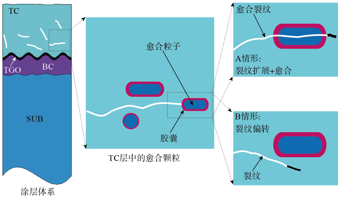
为突破传统热障涂层的失效瓶颈,自修复热障涂层(Self-healing thermal barrier coatings,SH–TBCs)通过引入功能化修复剂[ OUYANG T Y, WU J Y, YASIR M, et al. Effect of TiC self-healing coatings on the cyclic oxidation resistance and lifetime of thermal barrier coatings[J]. Journal of Alloys and Compounds, 2016, 656: 992–1003. 17],构建“损伤感知–修复剂释放–裂纹愈合”的智能响应机制。自修复材料包括聚合物[ WU D Y, MEURE S, SOLOMON D. Self-healing polymeric materials: A review of recent developments[J]. Progress in Polymer Science, 2008, 33(5): 479–522. CORDIER P, TOURNILHAC F, SOULIÉ-ZIAKOVIC C, et al. Self-healing and thermoreversible rubber from supramolecular assembly[J]. Nature, 2008, 451(7181): 977–980. 18-19]、金属[ NI W Y, CHENG Y T, GRUMMON D S. Recovery of microindents in a nickel–titanium shape-memory alloy: A “self-healing” effect[J]. Applied Physis Letters, 2002, 80(18): 3310–3312. NOSONOVSKY M, AMANO R, LUCCI J M, et al. Physical chemistry of self-organization and self-healing in metals[J]. Physical Chemistry Chemical Physics, 2009, 11(41): 9530–9536. SHCHUKIN D G, ZHELUDKEVICH M, YASAKAU K, et al. Layer-by-layer assembled nanocontainers for self-healing corrosion protection[J]. Advanced Materials, 2006, 18(13): 1672–1678. 20-22]、陶瓷[ WIKTOR V, JONKERS H M. Quantification of crack-healing in novel bacteria-based self-healing concrete[J]. Cement and Concrete Composites, 2011, 33(7): 763–770. MIHASHI H, NISHIWAKI T. Development of engineered self-healing and self-repairing concrete-state-of-the-art report[J]. Journal of Advanced Concrete Technology, 2012, 10(5): 170–184. 23-24]及其复合材料[ FERGUSON J B, SCHULTZ B F, ROHATGI P K. Self-healing metals and metal matrix composites[J]. JOM, 2014, 66(6): 866–871. BODE S, BOSE R K, MATTHES S, et al. Self-healing metallopolymers based on cadmium bis(terpyridine) complex containing polymer networks[J]. Polymer Chemistry, 2013, 4(18): 4966–4973. 25-26],当这些材料在经历热力、机械或其他形式的损伤后,具备恢复其原有性能的能力[ WOOL R P. Self-healing materials: A review[J]. Soft Matter, 2008, 4(3): 400–418. 27]。Sloof团队提出了自修复热障涂层的概念,并研究了其在高温下的自修复机制[ DERELIOGLU Z, CARABAT A L, SONG G M, et al. On the use of B–alloyed MoSi2 particles as crack healing agents in yttria stabilized zirconia thermal barrier coatings[J]. Journal of the European Ceramic Society, 2015, 35(16): 4507–4511. 28]。如图1所示[ WANG L, SHAO F, ZHONG X H, et al. Tailoring of self-healing thermal barrier coatings via finite element method[J]. Applied Surface Science, 2018, 431: 60–74. 29],当涂层受到热应力或其他外部载荷时,涂层内部或界面会产生微裂纹,微裂纹扩展到靠近“胶囊”的区域时,“胶囊”会破裂并释放出一些自修复物质(通常是金属或合金材料),这些物质会填充裂纹,使裂纹无法继续扩展(A情形)。如果微裂纹绕过“胶囊”,则不会发生自修复(B情形)。Chen等[ CHEN Y, ZHANG X, VAN DER ZWAAG S, et al. Damage evolution in a self-healing air plasma sprayed thermal barrier coating containing self-shielding MoSi2 particles[J]. Journal of the American Ceramic Society, 2019, 102(8): 4899–4910. 30]进一步发展了自愈合热障涂层技术,通过在TBCs中添加被Al2O3壳包覆的含铝MoSi2愈合粒子,并研究了这些自修复粒子在热循环条件下的动力学行为,指出了未来改进提高自愈合效率以及自修复粒子如何改善涂层高温服役性能的方向。Wang等[ WANG L, MING C, ZHONG X H, et al. Microstructure and self-healing properties of multi-layered NiCoCrAlY/TAZ/YSZ thermal barrier coatings fabricated by atmospheric plasma spraying[J]. Applied Surface Science, 2019, 488: 246–260. 31]通过大气等离子喷涂技术制备多层NiCoCrAlY/TAZ/TC自修复热障涂层,并展示了其耐久性在高温下显著提高,为提升燃气轮机等高温部件的使用寿命提供了有效策略。Ouyang等[ OUYANG T Y, SUO J P. TiC-self-healing thermal barrier coating structures and oxidation resistance[J]. Surface and Coatings Technology, 2021, 412: 127065. 32]开发了一系列TiC自修复TBCs,发现该自修复涂层的综合性能比一般热障涂层的综合性能更好,在工业应用中具有巨大的潜力。这些研究结果均表明,在涂层中引入自修复材料,通过其高温下的自修复效应,可以提高热障涂层的高温抗氧化性及其服役寿命。
图1 大气等离子喷涂热障涂层自修复原理机制图[ WANG L, SHAO F, ZHONG X H, et al. Tailoring of self-healing thermal barrier coatings via finite element method[J]. Applied Surface Science, 2018, 431: 60–74. 29]
Fig.1 Schematic illustration of self-healing mechanism of TBCs[ WANG L, SHAO F, ZHONG X H, et al. Tailoring of self-healing thermal barrier coatings via finite element method[J]. Applied Surface Science, 2018, 431: 60–74. 29]
在涂层制备过程中,喷涂粉末颗粒形态、尺寸大小、融化状态、飞行轨迹以及在基体上的铺展行为的差异,常会导致涂层内部以及不同层之间会出现一定程度的起伏。自修复热障涂层界面处会出现界面几何形态的变化,使得界面处形貌较为复杂,呈现不规则、不均匀的结构特性。也进一步使得界面处应力分布不均匀,导致自修复热障涂层在随后的服役过程中容易在界面处出现不可预知的失效模式,进而导致整体涂层的翘曲或分层剥落失效。当前研究多聚焦于热障涂层理想界面下的残余应力分析[ XIAO Y Q, LIU Z Y, PENG X M, et al. Spallation mechanism of thermal barrier coatings with real interface morphology considering growth and thermal stresses based on fracture phase field[J]. Surface and Coatings Technology, 2023, 458: 129356. FERGUEN N, LECLERC W, LAMINI E S. Numerical investigation of thermal stresses induced interface delamination in plasma-sprayed thermal barrier coatings[J]. Surface and Coatings Technology, 2023, 461: 129449. MONTAKHABI F, POURSAEIDI E, RAHIMI J, et al. Investigation of the effect of BC layer surface roughness and TC layer porosity on stress values in plasma sprayed coatings based on SEM images[J]. Materials Today Communications, 2022, 33: 104737. YU C T, ZHANG L, BAO Z B, et al. Interfacial failure induced by dynamic evolutional stress of NiCoCrAlY–4YSZ TBCs during gradient thermal cycling: Effect of 4YSZ top coat thickness[J]. Surface and Coatings Technology, 2024, 477: 130408. LI Z D, ZHENG R G, LIN X P, et al. Finite element analysis of TGO thickness on stress distribution and evolution of 8YSZ thermal barrier coatings[J]. Journal of the American Ceramic Society, 2023, 106(1): 789–804. ZHAO W L, HU Z C, WANG L, et al. Effect of top-coat thickness and interface fluctuation on the residual stress in APS–TBCs[J]. Coatings, 2023, 13(9): 1659. 33-38],然而,自修复热障涂层特有的自修复层将重构局部应力场分布。
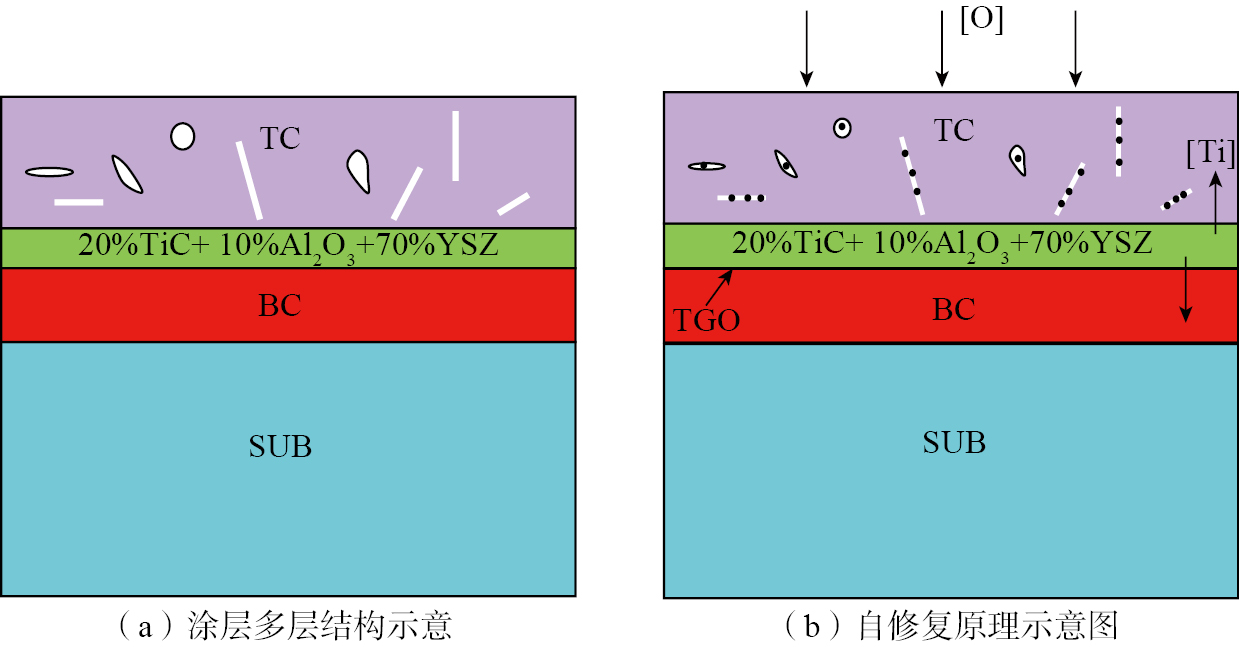
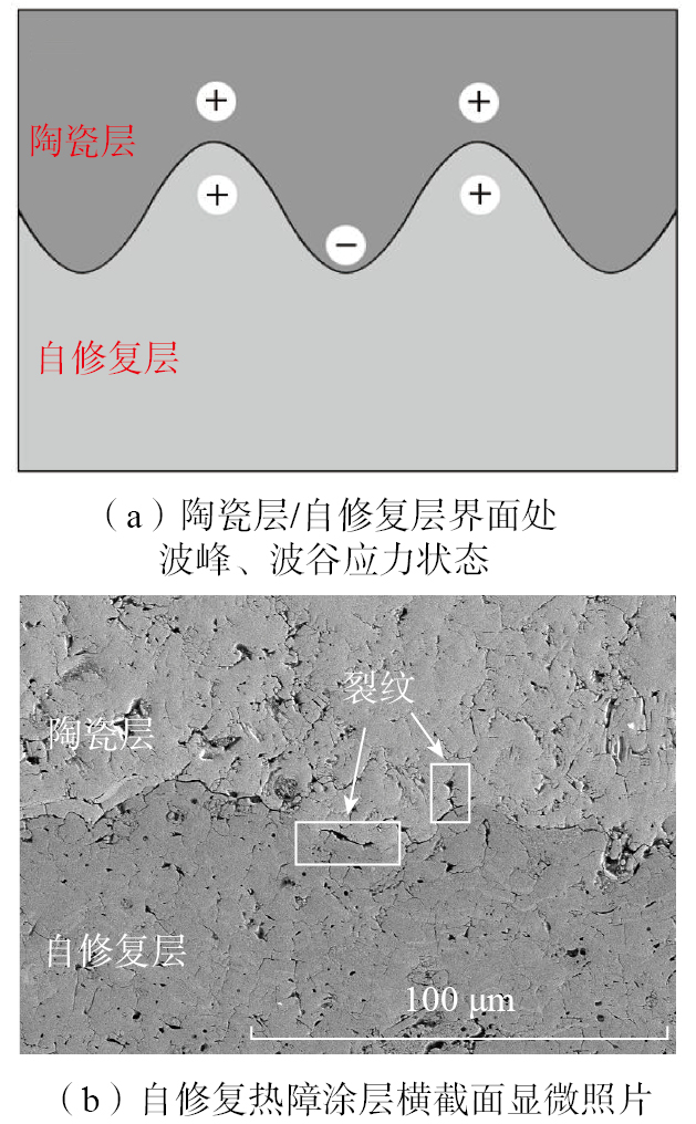
本文所研究的自修复热障涂层的结构设计建立在前期试验工作的基础上[ OUYANG T Y, SUO J P. TiC-self-healing thermal barrier coating structures and oxidation resistance[J]. Surface and Coatings Technology, 2021, 412: 127065. 32],在粘结层(Bond-coat,BC)和陶瓷层(Top-coat,TC)之间插入自修复层(TAZ),自修复层的成分包含质量分数20%的TiC、质量分数10%的Al2O3和质量分数70%的YSZ,如图2所示。自修复层中的Al2O3可以有效减少外部氧气向界面渗透扩散,降低TGO层的形成速率。加入YSZ是为了减少热膨胀系数的不匹配,减少热应力。自修复热障涂层的自修复效果主要依靠TAZ层中的TiC颗粒完成。当涂层暴露在高温氧化的环境时,TiC会与空气中的氧反应生成TiO2颗粒,这些颗粒能够填充裂纹间隙,因TiO2颗粒的密度低于TiC,裂纹周围会产生体积膨胀效应和压应力场,有助于裂纹的封闭。同时,TiO2的形成还能降低粘结层和YSZ层界面处氧的分压,进一步减缓TGO层的生长。
图2 自修复热障涂层的结构设计与自修复机理示意图
Fig.2 Schematic illustration diagram of structural design and self-healing mechanism of self-healing thermal barrier coatings
1.2 模型及边界条件
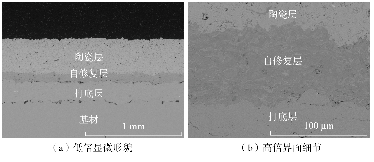
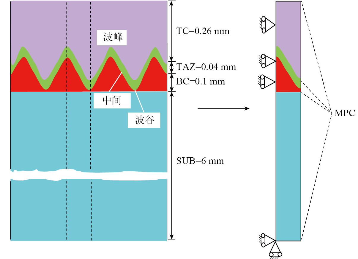
不同的TC/TAZ、TAZ/BC界面形貌对涂层的界面结合强度以及界面处涂层的残余应力状态有重要影响。采用ABAQUS有限元软件建立不同形貌的界面涂层模型,模型由厚度为260 μm的陶瓷层、40 μm的自修复层、100 μm的粘结层和6 mm的基体组成。TC/TAZ、TAZ/BC的界面粗糙度用理想余弦曲线y(x)=A·cos(2π(x+w)/L)(L为波长;A为界面振幅;w为上下界面相位差)表征,通过改变余弦曲线的L、A和w来研究界面粗糙度对应力的影响[ RANJBAR-FAR M, ABSI J, MARIAUX G, et al. Simulation of the effect of material properties and interface roughness on the stress distribution in thermal barrier coatings using finite element method[J]. Materials & Design, 2010, 31(2): 772–781. SFAR K, AKTAA J, MUNZ D. Numerical investigation of residual stress fields and crack behavior in TBC systems[J]. Materials Science and Engineering: A, 2002, 333(1–2): 351–360. 39-40],其中余弦界面的L为60~140 μm,A范围在5~30 μm之间[ REZVANI RAD M, FARRAHI G H, AZADI M, et al. Effects of preheating temperature and cooling rate on two-step residual stress in thermal barrier coatings considering real roughness and porosity effect[J]. Ceramics International, 2014, 40(10): 15925–15940. 41],这些值通常通过观察显微照片获得(图3)。由于几何模型具有对称性,且系统所受热载荷具有空间均匀性,因此多周期模型可以简化成半周期模型,如图4所示。半周期模型的左侧施加对称边界条件,左侧x方向位移为0;右侧施加多点约束(Multi-point constraint,MPC)来表征周期性边界条件。多点约束使右侧边的所有点可以同时沿x方向移动相同的位移且与y方向垂直。为保证计算精度,需在TC/TAZ/BC界面附近区域进行网格加密。假定涂层沉积到基体表面后快速铺展收缩,直到两者达到平衡温度,此时,整个系统设为处于427 ℃的高温[ LUGSCHEIDER E, NICKEL R. Finite element simulation of a coating formation on a turbine blade during plasma spraying[J]. Surface and Coatings Technology, 2003, 174: 475–481. 42](模拟涂层制备态温度,假定涂层系统处于零应力状态),涂层系统与室温空气发生自然热对流(对流换热系数为10 W/(m2·K)),大气温度设为25 ℃,制备后试样冷却18000 s(保证冷却时间足够长,整个涂层心部和表面侧面都处于热平衡状态)。
图3 自修复热障涂层显微照片
Fig.3 Cross-section image of self-healing TBCs
图4 自修复涂层理想余弦模型示意图
Fig.4 Schematic illustration of self-healing TBCs with the ideal cosine curve
在有限元模拟计算中,做出以下假设:(1)涂层各层均假设为各向同性材料;(2)由于陶瓷层为脆性材料,陶瓷层被假定为线弹性,只有当Mises应力超过屈服强度时,涂层中才会产生裂纹,加速涂层的破坏过程;(3)模拟过程不考虑热辐射的影响;(4)假设整个涂层喷涂过程中及刚结束后(停止送粉)的温度都是427 ℃。陶瓷层、粘结层、基体、Al2O3以及TiC的材料参数分别见表2~6。其中,TAZ层的材料参数可通过均匀混合规则和对数规则得到,均匀混合规则是假设各组分均匀分布且应变连续,适用于各组分力学性能差异较小的情况。TAZ中YSZ占比高(质量分数70%),其热膨胀系数(CTE)与TiC、Al2O3差异较小,因此均匀混合规则可合理反映整体性能趋势。在对数规则中,假设各组分应力连续,则适用于多孔或非均匀结构。由于TAZ中存在自修复颗粒(TiC),其局部应力分布可能受界面效应影响,对数规则可补充评估应力集中区域的性能,结合两种规则的综合使用可更全面地描述TAZ层的宏观力学行为。根据混合规则,TAZ层的有效性能可表示为[ OUYANG T Y, SUO J P. TiC-self-healing thermal barrier coating structures and oxidation resistance[J]. Surface and Coatings Technology, 2021, 412: 127065. 32]
表2 8YSZ的材料参数[ OUYANG T Y, SUO J P. TiC-self-healing thermal barrier coating structures and oxidation resistance[J]. Surface and Coatings Technology, 2021, 412: 127065. 32]
Table 2 Material parameters of 8YSZ[ OUYANG T Y, SUO J P. TiC-self-healing thermal barrier coating structures and oxidation resistance[J]. Surface and Coatings Technology, 2021, 412: 127065. 32]
温度/℃
密度/(kg/m3)
弹性模量/GPa
泊松比
热膨胀系数/(×10–6/K)
比热容/(J/(kg·K))
热导率/(W/(m·K))
20
5280
48
0.1
10.4
640
1.8
200
5280
47
0.1
10.5
640
1.76
500
5280
43
0.1
10.7
640
1.75
700
5280
39
0.11
10.8
640
1.72
1100
5280
25
0.12
10.9
640
1.69
1200
5280
22
0.12
11
640
1.67
1400
5280
15
0.12
11.3
640
1.62
表3 NiCoCrAlY的材料参数[ OUYANG T Y, SUO J P. TiC-self-healing thermal barrier coating structures and oxidation resistance[J]. Surface and Coatings Technology, 2021, 412: 127065. 32]
Table 3 Material parameters of NiCoCrAlY[ OUYANG T Y, SUO J P. TiC-self-healing thermal barrier coating structures and oxidation resistance[J]. Surface and Coatings Technology, 2021, 412: 127065. 32]
温度/℃
密度/(kg/m3)
弹性模量/GPa
泊松比
热膨胀系数/(×10–6/K)
比热容/(J/(kg·K))
热导率/(W/(m·K))
屈服强度/MPa
剪切模量/GPa
20
7320
152.4
0.1
12.3
501
4.3
270
5
200
7320
143.3
0.1
13.2
547
5.2
—
—
500
7320
136.7
0.1
14.7
598
6.4
—
—
700
7320
126.4
0.11
15.9
638
8.6
—
—
1100
7320
41.3
0.12
17.7
781
10.2
—
—
1200
7320
36.7
0.12
18.2
764
16.1
—
—
1400
7320
29.2
0.12
18.6
779
16.9
—
—
表4 高温合金基体的材料参数[ OUYANG T Y, SUO J P. TiC-self-healing thermal barrier coating structures and oxidation resistance[J]. Surface and Coatings Technology, 2021, 412: 127065. 32]
Table 4 Material parameters of high temperature alloy substrate[ OUYANG T Y, SUO J P. TiC-self-healing thermal barrier coating structures and oxidation resistance[J]. Surface and Coatings Technology, 2021, 412: 127065. 32]
温度/℃
密度/(kg/m3)
弹性模量/GPa
泊松比
热膨胀系数/(×10–6/K)
比热容/(J/(kg·K))
热导率/(W/(m·K))
屈服强度/MPa
剪切模量/GPa
20
8150
220
0.31
14.8
658
20
627
79
200
8150
210
0.32
15.2
667
21.1
—
—
400
8150
190
0.33
15.6
680
22.4
—
—
600
8150
170
0.33
16.2
690
23.6
—
—
800
8150
155
0.33
16.9
696
24.2
—
—
1000
8150
130
0.35
17.5
716
25.6
—
—
表5 TiC的物性参数[ ZHUANG M X, YUAN J H, HU Z C, et al. Design and optimization of coating structure for plasma sprayed self-healing MgO coating via finite element method[J]. Ceramics International, 2021, 47(2): 2414–2429. 43]
Table 5 Physical parameters of TiC[ ZHUANG M X, YUAN J H, HU Z C, et al. Design and optimization of coating structure for plasma sprayed self-healing MgO coating via finite element method[J]. Ceramics International, 2021, 47(2): 2414–2429. 43]
温度/℃
密度/(kg/m3)
弹性模量/GPa
泊松比
热膨胀系数/(×10–6/K)
比热容/(J/(kg·K))
热导率/(W/(m·K))
20
4940
500
0.16
6.4
564
24.3
27
4940
500
0.16
6.4
565
24.3
127
4940
495
0.16
6.7
692
24.3
227
4940
490
0.16
6.9
754
24.3
327
4940
485
0.16
7.1
790
24.3
427
4940
480
0.16
7.4
814
24.3
527
4940
475
0.16
7.6
832
24.3
627
4940
470
0.16
7.9
846
24.3
727
4940
465
0.16
8.1
857
24.3
927
4940
455
0.16
8.6
892
24.3
1127
4940
450
0.16
9.1
892
24.3
1327
4940
445
0.16
9.7
906
24.3
表6 Al2O3的物性参数[ HAN M, HUANG J H, CHEN S H. Behavior and mechanism of the stress buffer effect of the inside ceramic layer to the top ceramic layer in a double-ceramic-layer thermal barrier coating[J]. Ceramics International, 2014, 40(2): 2901–2914. 44]
Table 6 Physical parameters of Al2O3[ HAN M, HUANG J H, CHEN S H. Behavior and mechanism of the stress buffer effect of the inside ceramic layer to the top ceramic layer in a double-ceramic-layer thermal barrier coating[J]. Ceramics International, 2014, 40(2): 2901–2914. 44]
温度/℃
密度/(kg/m3)
弹性模量/GPa
泊松比
热膨胀系数/(×10–6/K)
比热容/(J/(kg·K))
热导率/(W/(m·K))
20
4200
400
0.23
7.13
980
9.8
200
4200
390
0.23
7.47
980
7.79
500
4200
376
0.25
8.57
980
6.21
800
4200
355
0.25
9.0
980
5.42
1000
4200
325
0.25
9.5
980
5.38
1100
4200
315
0.25
9.7
980
5.26
1400
4200
310
0.26
9.8
980
5.23
根据对数规律,TAZ的有效性质可表示为
(3)
因此,可以通过式(4)来得到TAZ的整体属性。
(4)
2 数值计算结果及分析
2.1 界面波长的影响
为了方便表征,将TC/TAZ界面设置为界面Ⅰ,TAZ/BC间的界面设置为界面Ⅱ。改变界面Ⅰ、Ⅱ的波长,界面Ⅰ、Ⅱ的幅值保持10 μm不变,w设为0。图5是不同界面不同波长自修复热障涂层系统冷却后至室温后的残余应力S22应力分布云图。由于热膨胀系数不匹配和界面Ⅰ、Ⅱ的界面起伏,界面Ⅰ、Ⅱ附近出现了明显的应力水平。由于粘结层的CTE大于TAZ,因此,粘结层在TAZ上引起波峰处的拉伸应力和波谷的压应力,即界面Ⅱ的波峰为拉应力,波谷为压应力。TC的CTE大于TAZ,因此TC在TAZ上引起波峰处的压应力和波谷的拉伸应力,即界面Ⅰ的波峰为拉应力,波谷为压应力。这些结果与Ranjbar[ RANJBAR-FAR M, ABSI J, MARIAUX G, et al. Simulation of the effect of material properties and interface roughness on the stress distribution in thermal barrier coatings using finite element method[J]. Materials & Design, 2010, 31(2): 772–781. 39]、Aktaa[ AKTAA J, SFAR K, MUNZ D. Assessment of TBC systems failure mechanisms using a fracture mechanics approach[J]. Acta Materialia, 2005, 53(16): 4399–4413. 45]、Hsueh[ HSUEH C H, FULLER E R. Residual stresses in thermal barrier coatings: Effects of interface asperity curvature/height and oxide thickness[J]. Materials Science and Engineering: A, 2000, 283(1–2): 46–55. 46]等的结果吻合,与理论认识一致。从图5可以看出,冷却后,界面Ⅰ、Ⅱ的定性分布保持不变。并且,随着波长的增加,TBC、TC中受拉的面积增加。
图5 不同波长下的S22应力分布云图
Fig.5S22 stress distribution with different wavelengths
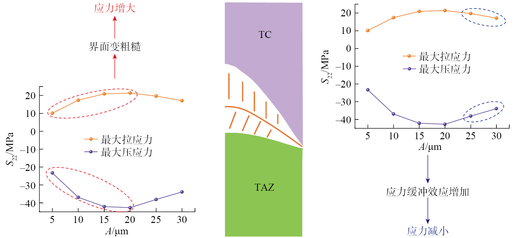
如果界面的振幅A值较小(5~20 μm),则随着A的增加,界面会变得粗糙。界面波峰波谷处变得更尖锐,波峰波谷处的应力集中会更加明显,导致应力增大[ HAN M, HUANG J H, CHEN S H. The influence of interface morphology on the stress distribution in double-ceramic-layer thermal barrier coatings[J]. Ceramics International, 2015, 41(3): 4312–4325. 47]。振幅变大时,可以从应力云图看到拉应力区域面积变大,且最大拉应力位置往左边移动。在自修复涂层的设计时,考虑到材料参数的不同,TAZ层在降低TC层中的应力水平时具有应力缓冲作用。随着振幅A的进一步增大,界面附近的TAZ层面积将增加,TC层的面积将减小。最后,界面附近的应力缓冲效应将增加,并且应力缓冲效应对应力的影响将大于来自上述粗糙界面的影响,即最大应力减小,如图10所示。
图10 TAZ与TC界面幅值增加导致的界面应力变化解释示意图
Fig.10 Schematic diagram explaining the change in interface stress caused by the increase of interface amplitude between TAZ and TC
界面Ⅰ、Ⅱ都是由y(x)=A·cos(2π(x+w)/L)(L为波长;A为界面振幅;w为界面相位差)构成。为了研究界面Ⅰ和Ⅱ的交互影响,对于界面Ⅱ,w为0;而对于界面Ⅰ,需改变w来表征两个界面间可能的微观结构模式[ CHEN Q, HU P, PU J, et al. Interfacial interaction and roughness parameters effects on the residual stresses in DCL–TBC system with different thickness distributions[J]. Ceramics International, 2021, 47(2): 2781–2792. 16]。用d来表示界面两个峰之间的水平距离,两个界面的波长均为100 μm,振幅均为10 μm。
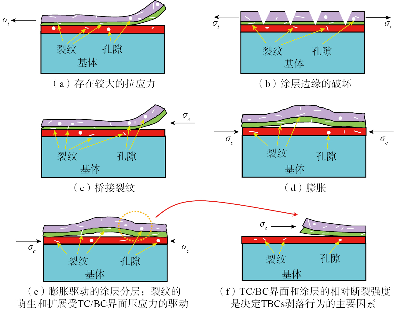
图13 TBCs在不同残余应力状态下的失效模式 [ ZHAO W L, HU Z C, WANG L, et al. Effect of top-coat thickness and interface fluctuation on the residual stress in APS–TBCs[J]. Coatings, 2023, 13(9): 1659. 38]
Fig.13 Failure modes of self-healing TBCs under different residual stress states[ ZHAO W L, HU Z C, WANG L, et al. Effect of top-coat thickness and interface fluctuation on the residual stress in APS–TBCs[J]. Coatings, 2023, 13(9): 1659. 38]
THAKAREJ G, PANDEYC, MAHAPATRAM M, et al. Thermal barrier coatings—A state of the art review[J]. Metals and Materials International, 2021, 27(7): 1947–1968.
[2]
PADTUREN P, GELLM, JORDANE H. Thermal barrier coatings for gas-turbine engine applications[J]. Science, 2002, 296(5566): 280–284.
[3]
GOSWAMIB, RAYA K, SAHAYS K. Thermal barrier coating system for gas turbine application—A review[J]. High Temperature Materials and Processes, 23(2): 73–92.
[4]
EVANSA G, MUMMD R, HUTCHINSONJ W, et al. Mechanisms controlling the durability of thermal barrier coatings[J]. Progress in Materials Science, 2001, 46(5): 505–553.
[5]
DAIH W, ZHANGJ H, RENY Y, et al. Failure mechanism of thermal barrier coatings of an ex-service aero-engine combustor[J]. Surface and Coatings Technology, 2019, 380: 125030.
[6]
BUSSOE P, WRIGHTL, EVANSH E, et al. A physics-based life prediction methodology for thermal barrier coating systems[J]. Acta Materialia, 2007, 55(5): 1491–1503.
[7]
SCHLICHTINGK W, PADTUREN P, JORDANE H, et al. Failure modes in plasma-sprayed thermal barrier coatings[J]. Materials Science and Engineering: A, 2003, 342(1–2): 120–130.
[8]
ABUBAKARA A, ARIFA F M, AKHTARS S. Evolution of internal cracks and residual stress during deposition of TBC[J]. Ceramics International, 2020, 46(17): 26731–26753.
[9]
KUMARV, BALASUBRAMANIANK. Progress update on failure mechanisms of advanced thermal barrier coatings: A review[J]. Progress in Organic Coatings, 2016, 90: 54–82.
[10]
MEHBOOBG, LIUM J, XUT, et al. A review on failure mechanism of thermal barrier coatings and strategies to extend their lifetime[J]. Ceramics International, 2020, 46(7): 8497–8521.
[11]
DASB, GOPINATHM, NATHA K, et al. Effect of cooling rate on residual stress and mechanical properties of laser remelted ceramic coating[J]. Journal of the European Ceramic Society, 2018, 38(11): 3932–3944.
[12]
ZHAOS M, YANP T, LIM, et al. Residual stress evolution of 8YSZ: Eu coating during thermal cycling studied by Eu3+ photoluminescence piezo-spectroscopy[J]. Journal of Alloys and Compounds, 2022, 913: 165292.
[13]
WANGL, WANGY, SUNX G, et al. Microstructure and surface residual stress of plasma sprayed nanostructured and conventional ZrO2–8wt%Y2O3 thermal barrier coatings[J]. Surface and Interface Analysis, 2011, 43(5): 869–880.
[14]
WANGL, LID C, YANGJ S, et al. Modeling of thermal properties and failure of thermal barrier coatings with the use of finite element methods: A review[J]. Journal of the European Ceramic Society, 2016, 36(6): 1313–1331.
[15]
CENL, QINW Y, YUQ M. Analysis of interface delamination in thermal barrier coating system with axisymmetric structure based on corresponding normal and tangential stresses[J]. Surface and Coatings Technology, 2019, 358: 785–795.
[16]
CHENQ, HUP, PUJ, et al. Interfacial interaction and roughness parameters effects on the residual stresses in DCL–TBC system with different thickness distributions[J]. Ceramics International, 2021, 47(2): 2781–2792.
[17]
OUYANGT Y, WUJ Y, YASIRM, et al. Effect of TiC self-healing coatings on the cyclic oxidation resistance and lifetime of thermal barrier coatings[J]. Journal of Alloys and Compounds, 2016, 656: 992–1003.
[18]
WUD Y, MEURES, SOLOMOND. Self-healing polymeric materials: A review of recent developments[J]. Progress in Polymer Science, 2008, 33(5): 479–522.
[19]
CORDIERP, TOURNILHACF, SOULIÉ-ZIAKOVICC, et al. Self-healing and thermoreversible rubber from supramolecular assembly[J]. Nature, 2008, 451(7181): 977–980.
[20]
NIW Y, CHENGY T, GRUMMOND S. Recovery of microindents in a nickel–titanium shape-memory alloy: A “self-healing” effect[J]. Applied Physis Letters, 2002, 80(18): 3310–3312.
[21]
NOSONOVSKYM, AMANOR, LUCCIJ M, et al. Physical chemistry of self-organization and self-healing in metals[J]. Physical Chemistry Chemical Physics, 2009, 11(41): 9530–9536.
[22]
SHCHUKIND G, ZHELUDKEVICHM, YASAKAUK, et al. Layer-by-layer assembled nanocontainers for self-healing corrosion protection[J]. Advanced Materials, 2006, 18(13): 1672–1678.
[23]
WIKTORV, JONKERSH M. Quantification of crack-healing in novel bacteria-based self-healing concrete[J]. Cement and Concrete Composites, 2011, 33(7): 763–770.
[24]
MIHASHIH, NISHIWAKIT. Development of engineered self-healing and self-repairing concrete-state-of-the-art report[J]. Journal of Advanced Concrete Technology, 2012, 10(5): 170–184.
[25]
FERGUSONJ B, SCHULTZB F, ROHATGIP K. Self-healing metals and metal matrix composites[J]. JOM, 2014, 66(6): 866–871.
[26]
BODES, BOSER K, MATTHESS, et al. Self-healing metallopolymers based on cadmium bis(terpyridine) complex containing polymer networks[J]. Polymer Chemistry, 2013, 4(18): 4966–4973.
[27]
WOOLR P. Self-healing materials: A review[J]. Soft Matter, 2008, 4(3): 400–418.
[28]
DERELIOGLUZ, CARABATA L, SONGG M, et al. On the use of B–alloyed MoSi2 particles as crack healing agents in yttria stabilized zirconia thermal barrier coatings[J]. Journal of the European Ceramic Society, 2015, 35(16): 4507–4511.
[29]
WANGL, SHAOF, ZHONGX H, et al. Tailoring of self-healing thermal barrier coatings via finite element method[J]. Applied Surface Science, 2018, 431: 60–74.
[30]
CHENY, ZHANGX, VAN DER ZWAAGS, et al. Damage evolution in a self-healing air plasma sprayed thermal barrier coating containing self-shielding MoSi2 particles[J]. Journal of the American Ceramic Society, 2019, 102(8): 4899–4910.
[31]
WANGL, MINGC, ZHONGX H, et al. Microstructure and self-healing properties of multi-layered NiCoCrAlY/TAZ/YSZ thermal barrier coatings fabricated by atmospheric plasma spraying[J]. Applied Surface Science, 2019, 488: 246–260.
[32]
OUYANGT Y, SUOJ P. TiC-self-healing thermal barrier coating structures and oxidation resistance[J]. Surface and Coatings Technology, 2021, 412: 127065.
[33]
XIAOY Q, LIUZ Y, PENGX M, et al. Spallation mechanism of thermal barrier coatings with real interface morphology considering growth and thermal stresses based on fracture phase field[J]. Surface and Coatings Technology, 2023, 458: 129356.
[34]
FERGUENN, LECLERCW, LAMINIE S. Numerical investigation of thermal stresses induced interface delamination in plasma-sprayed thermal barrier coatings[J]. Surface and Coatings Technology, 2023, 461: 129449.
[35]
MONTAKHABIF, POURSAEIDIE, RAHIMIJ, et al. Investigation of the effect of BC layer surface roughness and TC layer porosity on stress values in plasma sprayed coatings based on SEM images[J]. Materials Today Communications, 2022, 33: 104737.
[36]
YUC T, ZHANGL, BAOZ B, et al. Interfacial failure induced by dynamic evolutional stress of NiCoCrAlY–4YSZ TBCs during gradient thermal cycling: Effect of 4YSZ top coat thickness[J]. Surface and Coatings Technology, 2024, 477: 130408.
[37]
LIZ D, ZHENGR G, LINX P, et al. Finite element analysis of TGO thickness on stress distribution and evolution of 8YSZ thermal barrier coatings[J]. Journal of the American Ceramic Society, 2023, 106(1): 789–804.
[38]
ZHAOW L, HUZ C, WANGL, et al. Effect of top-coat thickness and interface fluctuation on the residual stress in APS–TBCs[J]. Coatings, 2023, 13(9): 1659.
[39]
RANJBAR-FARM, ABSIJ, MARIAUXG, et al. Simulation of the effect of material properties and interface roughness on the stress distribution in thermal barrier coatings using finite element method[J]. Materials & Design, 2010, 31(2): 772–781.
[40]
SFARK, AKTAAJ, MUNZD. Numerical investigation of residual stress fields and crack behavior in TBC systems[J]. Materials Science and Engineering: A, 2002, 333(1–2): 351–360.
[41]
REZVANI RADM, FARRAHIG H, AZADIM, et al. Effects of preheating temperature and cooling rate on two-step residual stress in thermal barrier coatings considering real roughness and porosity effect[J]. Ceramics International, 2014, 40(10): 15925–15940.
[42]
LUGSCHEIDERE, NICKELR. Finite element simulation of a coating formation on a turbine blade during plasma spraying[J]. Surface and Coatings Technology, 2003, 174: 475–481.
[43]
ZHUANGM X, YUANJ H, HUZ C, et al. Design and optimization of coating structure for plasma sprayed self-healing MgO coating via finite element method[J]. Ceramics International, 2021, 47(2): 2414–2429.
[44]
HANM, HUANGJ H, CHENS H. Behavior and mechanism of the stress buffer effect of the inside ceramic layer to the top ceramic layer in a double-ceramic-layer thermal barrier coating[J]. Ceramics International, 2014, 40(2): 2901–2914.
[45]
AKTAAJ, SFARK, MUNZD. Assessment of TBC systems failure mechanisms using a fracture mechanics approach[J]. Acta Materialia, 2005, 53(16): 4399–4413.
[46]
HSUEHC H, FULLERE R. Residual stresses in thermal barrier coatings: Effects of interface asperity curvature/height and oxide thickness[J]. Materials Science and Engineering: A, 2000, 283(1–2): 46–55.
[47]
HANM, HUANGJ H, CHENS H. The influence of interface morphology on the stress distribution in double-ceramic-layer thermal barrier coatings[J]. Ceramics International, 2015, 41(3): 4312–4325.