管材在航空、航天、汽车、船舶中应用广泛[1],主要用于介质输送。在飞行器和动力装置中,为了达到减轻整体质量、增加可用空间的目的,对于相对弯曲半径小于2(相对弯曲半径指弯曲半径与管材外径之比)的小弯曲半径管材的需求越来越大[2-3]。目前,传统管材弯曲技术对小弯曲半径管材的加工研究已经颇有成果,学者们提出使用绕弯和推弯的方式加工小弯曲半径管材。李恒等[4-5]针对大口径、小弯曲半径管材的数控绕弯成形进行了有限元模拟及试验,分析了弯曲过程中应力应变和管材失稳起皱的演变过程,同时通过试验验证了有限元模拟的可靠性。岳永保等[6]对薄壁管小弯曲半径数控弯曲的壁厚减薄进行了试验研究,分析了芯棒伸出量、芯头个数、弯曲角度、压块参数、相对弯曲半径、材料参数对壁厚减薄的影响。推弯成形技术目前已经可以加工相对弯曲半径为1 的管材,并对各种材料管材进行了推弯成形研究。曾元松等[7]对铝合金管材的内压推弯成形过程进行了数值模拟,试验表明,在合理的内压力和摩擦润滑条件下,可成形出相对弯曲半径为1的小弯曲半径管件。黄遐等[8]基于不锈钢管材的小弯曲半径管内压推弯成形过程进行了有限元模拟,并通过试验验证了模拟结果,最终建立了不锈钢小弯曲半径管的最佳内压力成形曲线。方继钊[9]、Xiao[10]等研究了GH4169 高温合金薄壁管小弯曲半径的冷胀推弯成形,针对1D 弯曲半径的推弯成形提出了最优的润滑方式和工艺条件。李鹏亮等[11]进行了钛合金管材的小弯曲半径弯曲成形技术研究,通过推弯成形的方式,利用内压力成形了质量较好的薄壁小弯曲半径管材。然而,绕弯、推弯等传统管材弯曲方法在加工管材时需对管材进行多约束形式加工[12-13],不利于成形连续多弯的复杂弯曲管材。
三维自由弯曲技术是一种新兴的管材塑性加工技术[14],可在三维空间内对管材进行任意角度和形状弯曲的加工[15-16],国内外学者研究了其中的成形过程和成形极限[17]。Guo 等[18]通过改良弯曲模与导轨的连接形式,成形了相对弯曲半径为2.5 的管材,并研究了不同弯曲半径下的管材成形特性。自由弯曲成形过程中,主要通过前端弯曲模对管材施加弯矩来成形管材[19],但是受本身强度以及自由度的影响,所施加的弯矩并不能成形小弯曲半径管材[20]。
本文在上述研究的基础上,基于ABAQUS 有限元模拟建立自由弯曲成形的有限元模型,分析小弯曲半径管材的成形过程,并通过增加附加弯矩的方式来成形相对弯曲半径小于2 的管材,探究在增加凸轮工装时可成形的管材弯曲半径极限,并通过试验证明了有限元模型的有效性。
1 自由弯曲技术基本原理
三维自由弯曲成形的主要技术原理如图1所示。自由弯曲的成形过程主要由管材进给和弯曲模的偏移、旋转共同完成。图1中,导向机构中心轴线与弯曲模中心轴线在Z 方向的偏移距离为U;弯曲模中心与导向机构前端距离为A;管材Y 向送料速度为v;弯曲模施加弯矩为M,凸轮对管材施加弯矩为MH。
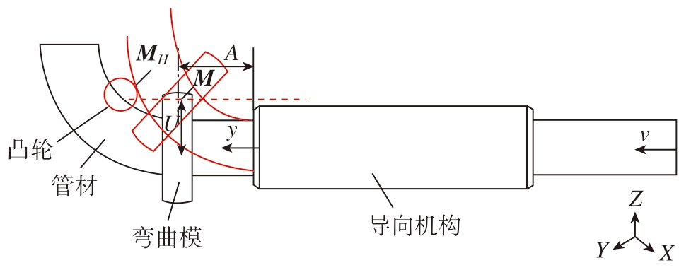
图1 自由弯曲原理及弯矩示意图
Fig.1 Schematic diagram of free bending principle and bending moment
在自由弯曲成形技术中,管材的弯曲半径R 由U值与A 值确定。然而,对于不同材质和壁厚的管材,相同的U 值与A 值成形出的管材弯曲半径也并不相同。所以在成形弯曲半径R 前,首先必须经过试验确定相对应的偏移距离U,进而制定相对应的成形工艺参数,主要包括弯曲模的弯曲角度变化参数、A 值和管材进给速率等。针对增加凸轮工装之后的加工成形,需要在加工试验前,通过模拟确定成形相应弯曲半径的H 值,即凸轮在Z 方向的偏移距离。
2 小弯曲半径成形有限元模拟试验
2.1 有限元模型的建立
2.1.1 几何模型
整体几何模型建立如图2所示,其中包括弯曲模、导向机构、芯棒、支撑机构、管材以及凸轮工装,管材采用壳单元,外径20 mm、壁厚2 mm、长度1500 mm。管材弯曲过程中主要受到弯曲模弯矩作用产生变形,将管材作为主要研究对象研究其变形过程,其他机构变形可忽略不计,因此可把它们视为刚体。
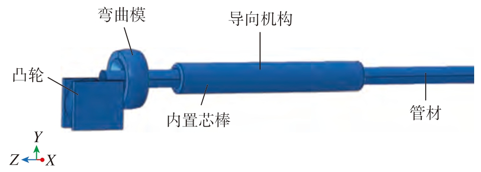
图2 有限元模型
Fig.2 Finite element model
2.1.2 单元格划分
在进行模型网格划分时,刚体部分采用全局尺寸设置,管材网格划分采用S4R 单元,有限元模型整体网格及凸轮网格如图3所示。

图3 模型网格划分
Fig.3 Model mesh division
(1)材料模型。
管材材料采用304 不锈钢,其塑性应力-应变曲线如图4所示,材料性能参数见表1。
表1 材料参数
Table 1 Material parameters
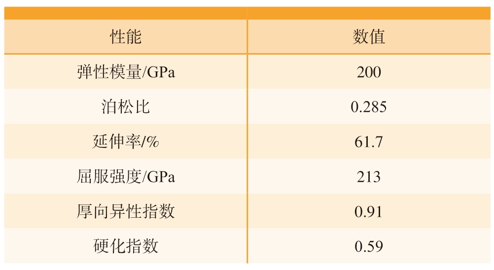
性能 数值弹性模量/GPa 200泊松比 0.285延伸率/% 61.7屈服强度/GPa 213厚向异性指数 0.91硬化指数 0.59
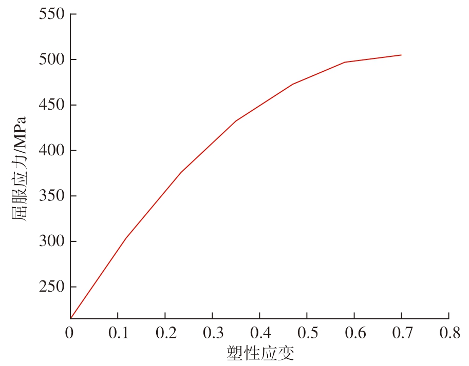
图4 304 不锈钢应力–应变曲线
Fig.4 Stress–strain curve of 304 stainless steel
(2)边界条件。
导向机构、支撑机构、芯棒保持固定,管材在Z 方向被推动,弯曲模存在Y 方向位移,并可绕X 轴转动,凸轮只存在Y 方向位移,其他自由度都固定。
(3)接触定义。
本模型中所有部件之间的接触全部设定为表面与表面接触,并施加显式罚接触方法。本文为了降低摩擦对管材成形的影响[21],在合理范围内设置较小的摩擦系数,因此设置全局摩擦系数为0.05。
(4)载荷施加。
本模拟中需要施加的载荷主要有3 个:管材沿Y 方向的进给速度v,设为30 mm/s;弯曲模偏移与旋转的幅值(图 5);凸轮在Y 方向偏移最大值H。
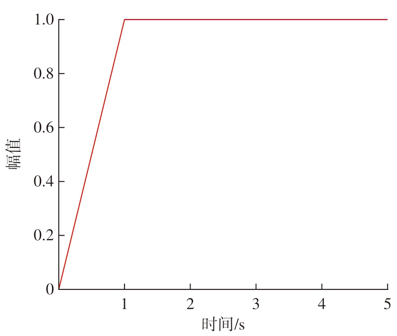
图5 幅值变化曲线
Fig.5 Variation curve of magnitude
2.2 模拟结果分析
选择不同工艺参数进行数值模拟,并计算不同参数下弯曲模对管材的弯矩,工艺参数见表2。在有限元模拟过程中,为了得到更加准确的模拟结果,分析步中采用显式动力学分析,质量缩放系数为10000 倍,输出自由弯曲成形的管型以及应力变化情况。
表2 有限元模拟参数设置
Table 2 Parameter settings for finite element simulation
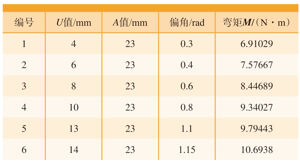
编号 U值/mm A值/mm 偏角/rad 弯矩M/(N·m)1 4 23 0.3 6.91029 2 6 23 0.4 7.57667 3 8 23 0.6 8.44689 4 10 23 0.8 9.34027 5 13 23 1.1 9.79443 6 14 23 1.15 10.6938
通过不同模拟参数成形的管材应力云图如图 6(a)所示,图中数字为参数设置序号。在此基础上利用Python 进行二次开发读取管材中心点坐标,在Catia 环境下绘制管材中心轴线形状,如图 6(b)所示。
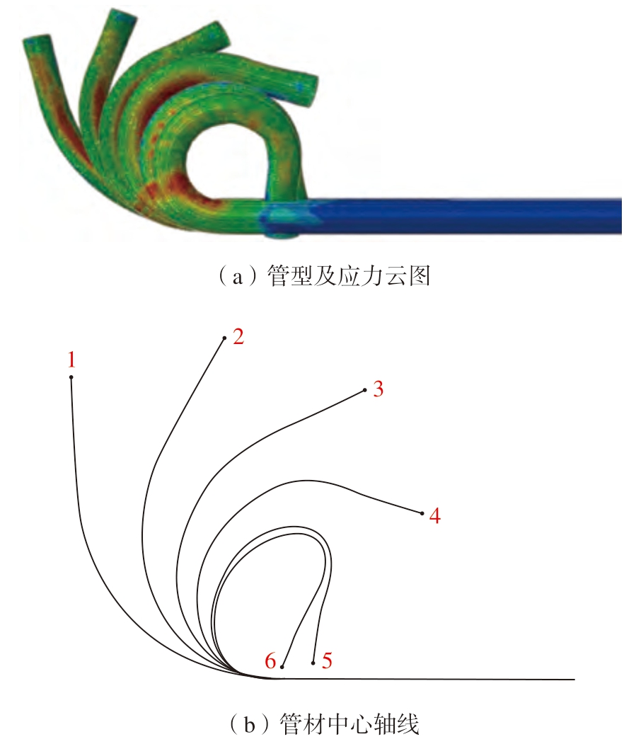
图6 不同U 值下成形管材的应力云图和管材中心轴线
Fig.6 Stress nephograms of formed pipes and the central axes of pipes under different U-values
利用Catia 中的曲率分析工具测得管材弯曲曲率,并绘制曲率1/R 与偏距U、曲率1/R 与弯矩M 之间的关系,如图7所示。
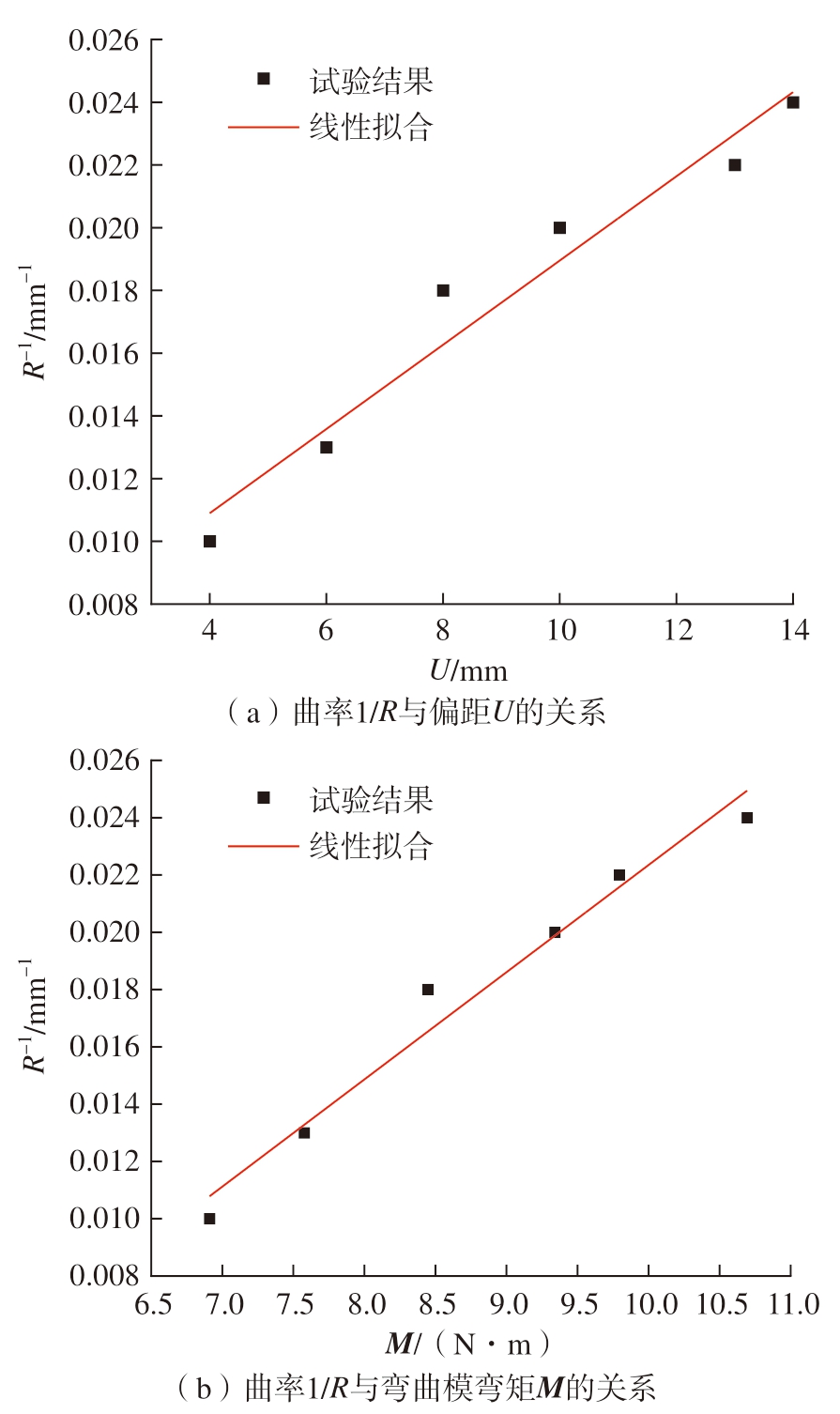
图7 曲率与偏距及弯矩之间的关系
Fig.7 Relationship between curvature, offset and bending moment
对曲线进行拟合处理,得到1/R 与U 之间的函数关系为

通过对比曲率与偏距、弯矩之间的关系可以得知,弯曲半径会随着偏距的增加而减小,随弯矩的增加而减小。通过模拟结果可知,在偏距U 为14 mm 时,弯曲半径达到最小值为41.4 mm,最小相对弯曲半径为2.07。
在弯曲模施加弯矩的基础上,增加凸轮工装从而对管材施加附加弯矩,工艺参数如表3所示,并计算凸轮对管材的弯矩。其中,AH 为凸轮中心点与固定模之间的距离;MH 为凸轮施加的附加弯矩。在使用凸轮工装进行小弯曲半径管材加工时,需要先将弯曲模偏移到指定位置,再将凸轮进给到试验偏移距离,进行管材加工成形。
表3 增加凸轮的工艺参数
Table 3 Process parameters for adding cam
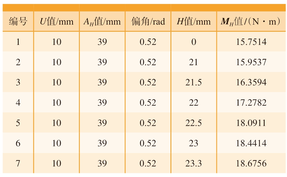
编号 U值/mm AH值/mm 偏角/rad H值/mm MH值 /(N·m)1 10 39 0.52 0 15.7514 2 10 39 0.52 21 15.9537 3 10 39 0.52 21.5 16.3594 4 10 39 0.52 22 17.2782 5 10 39 0.52 22.5 18.0911 6 10 39 0.52 23 18.4414 7 10 39 0.52 23.3 18.6756
在AbaqusCAE 环境下,模拟不同H 值的加工参数下的管材弯曲过程,得出管材的管型及应力云图,并提取轴线如图8所示。
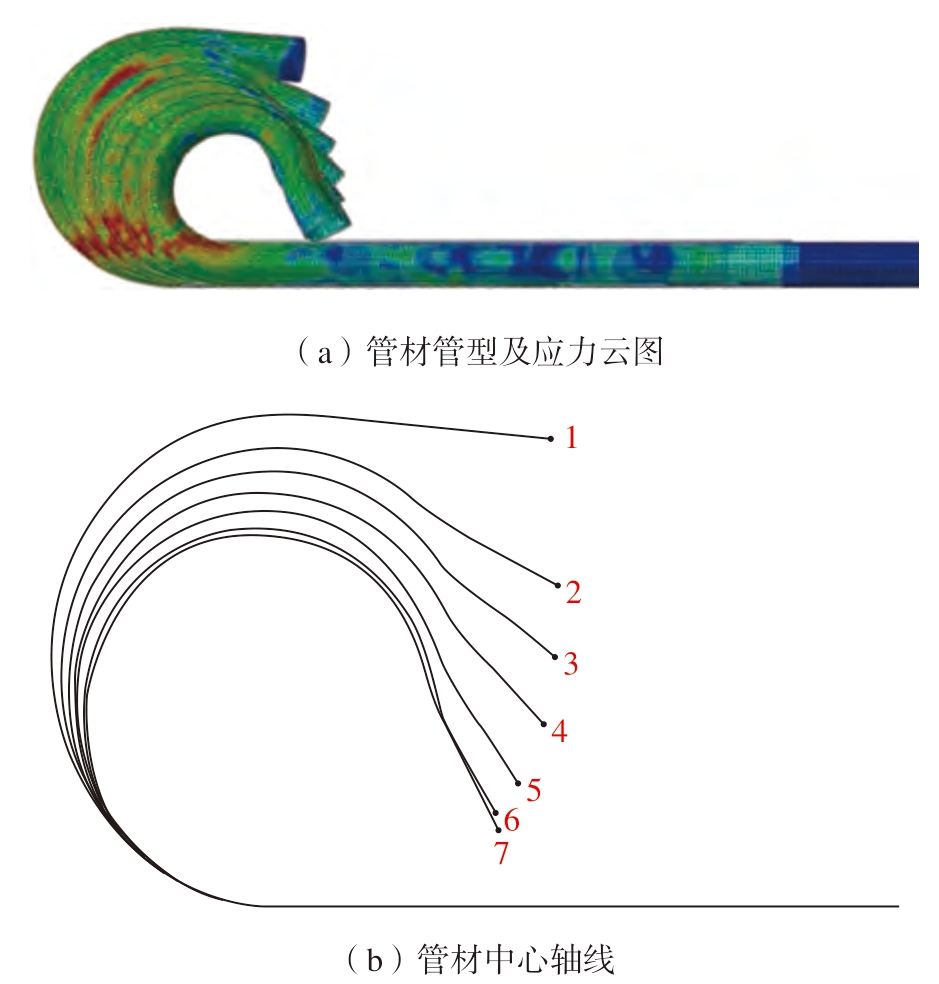
图8 不同工艺参数下管材的应力云图和管材中心轴线
Fig.8 Stress nephograms of pipes and the central axes of pipes under different process parameters
对不同工艺参数下管材的弯曲半径进行分析,得到管材弯曲半径与凸轮偏移距离H 值以及凸轮施加的附加弯矩MH 之间的关系,如图9所示。
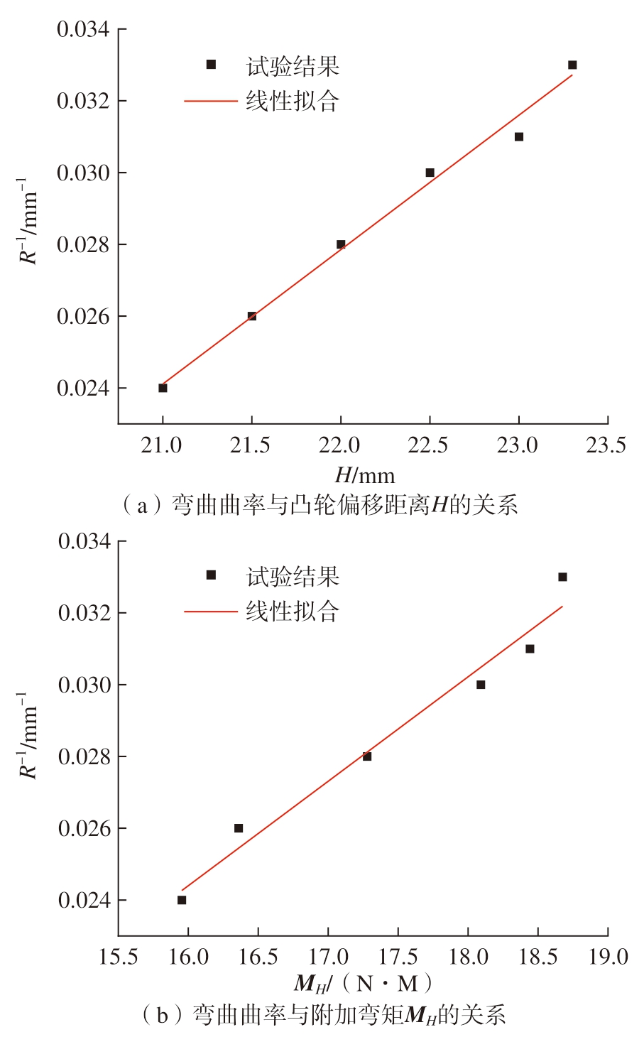
图9 弯曲曲率与H 及MH 的关系
Fig.9 Relationship between bending curvature and H, MH
通过对散点图进行线性拟合,得到1/R 与H、MH 的关系式,即
对比不同H 值的管材轴线图(图8(b)),可以发现在使用凸轮工装施加附加弯矩时可以有效减小管材弯曲半径,最小弯曲半径可以达到30 mm,最小相对弯曲半径为1.5,弯曲半径会随着H 值以及附加弯矩MH 的增加而减小。
3 试验验证
在有限元模拟的基础上进行了试验验证,弯曲试验在自主搭建的自由弯曲成形设备上进行,如图10所示。加工管材材料选用304不锈钢,管材外径为20mm,壁厚为2mm。通过改变U 值和偏角,从而获得不同弯曲半径的管材,加工参数见表4。
表4 加工参数
Table 4 Processing parameters
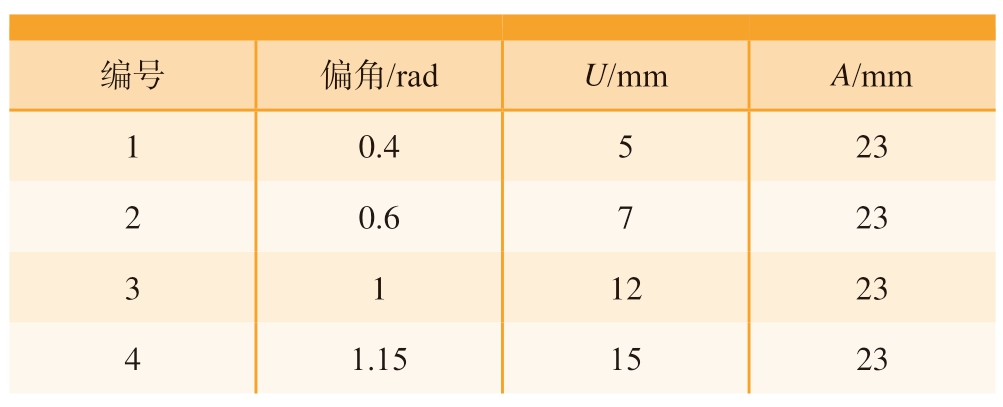
编号 偏角/rad U/mm A/mm 1 0.4 5 23 2 0.6 7 23 3 1 12 23 4 1.15 15 23
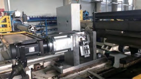
图10 自由弯曲试验平台
Fig.10 Free bending experimental platform
通过试验平台加工成形的管材如图11所示,使用P8 弯曲半径测量机按弯曲角度测量管材的弯曲半径和椭圆度,试验结果如图12所示。
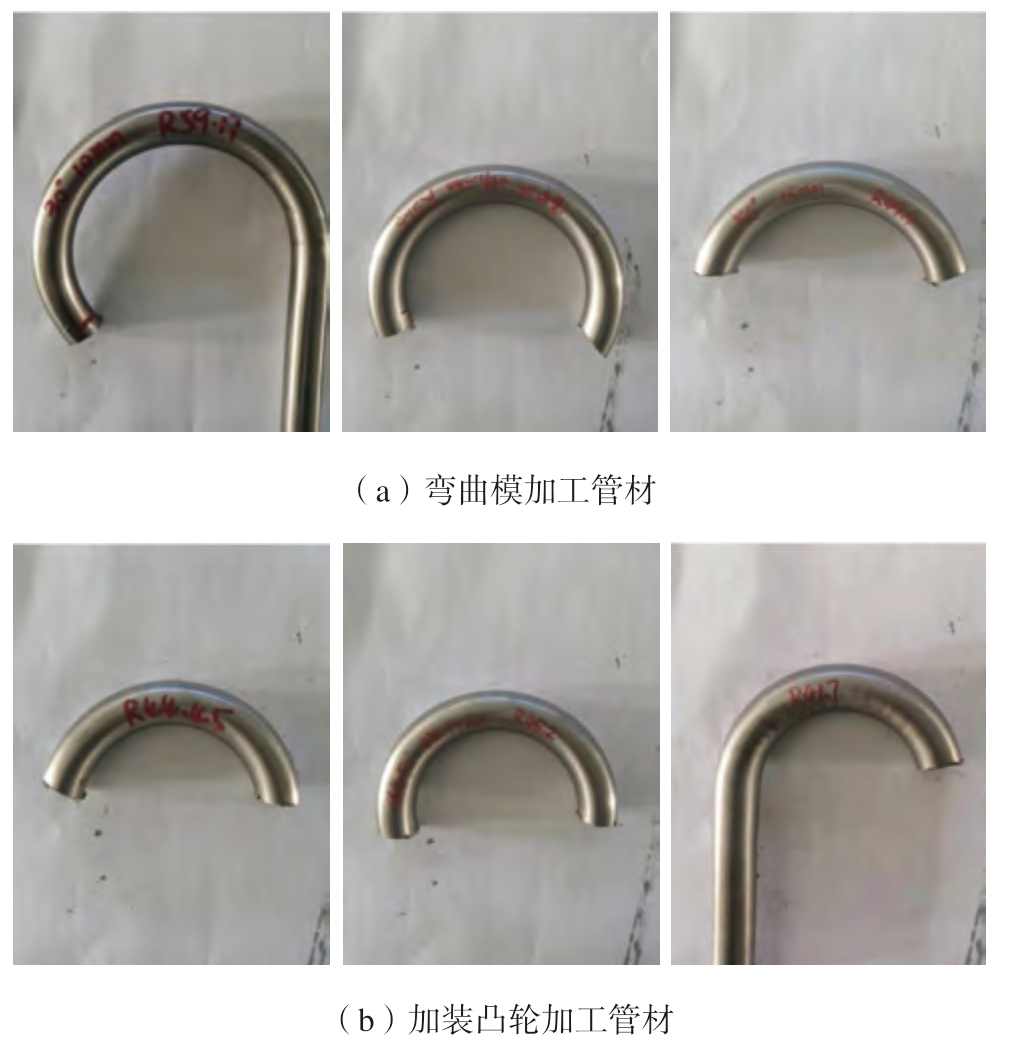
图11 加工管材实物图
Fig.11 Physical view of processed pipes
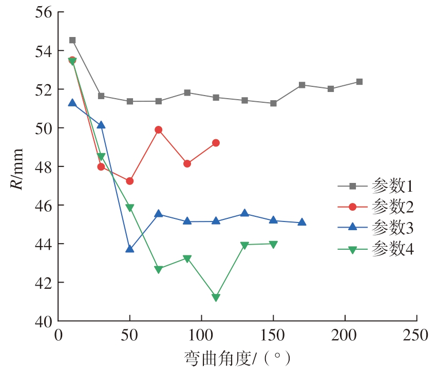
图12 不同U 值、不同弯曲角的管材弯曲半径
Fig.12 Bending radius of pipes under different U-values and different bending angles
选用相同的U 值、偏角、A 值和不同的H 值,如表5所示,试验结果如图13所示。可以看出,弯曲半径会随着U 值和H 值的增加而减小,与有限元模拟的结果一致,同时通过试验发现,可以达到最小弯曲半径为35 mm,最小相对弯曲半径为1.75。从图13(b)可以看出,管材的椭圆度会随H 值的增加而增大。
表5 加装凸轮的加工参数
Table 5 Processing parameters for installation of cam
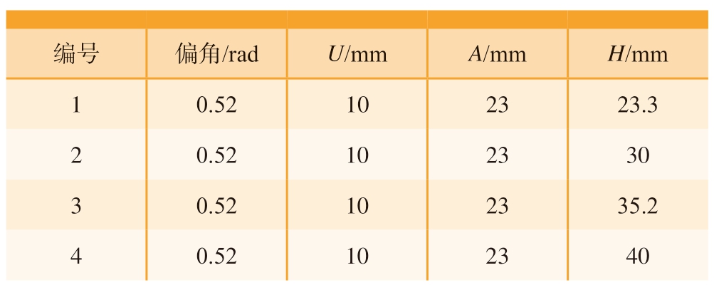
编号 偏角/rad U/mm A/mm H/mm 1 0.52 10 23 23.3 2 0.52 10 23 30 3 0.52 10 23 35.2 4 0.52 10 23 40
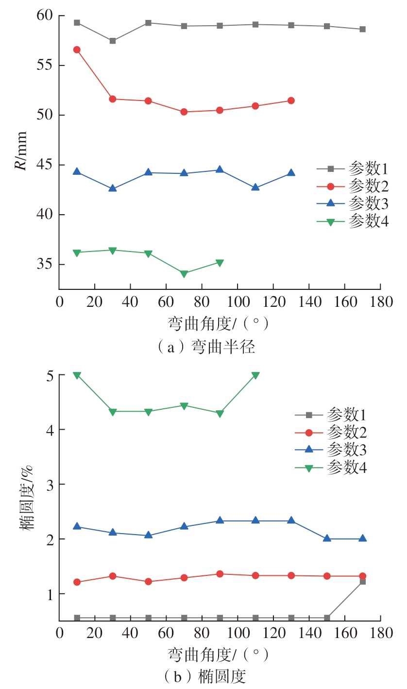
图13 不同H 值下管材不同弯曲角的弯曲半径和椭圆度关系
Fig.13 Relationship between bending radius and the ovality of the pipe with different bending angles under different H-values
4 结论
(1)有限元模拟结果说明,使用弯曲模进行自由弯曲成形时,可成形的最小相对弯曲半径为2.07。而通过增加凸轮工装增加附加弯矩的方式,能够有效成形相对弯曲半径小的管材,最小相对弯曲半径为1.5。进一步增加弯曲模的凸轮偏移可以成形弯曲半径更小的管材,但是偏移量过大容易引起管材的截面畸变。因此需要通过模拟试验确定合适的偏移距离和凸轮在Z 方向的偏移最大值。通过模拟结果研究发现,弯曲半径会随着弯曲模的偏移距离和施加弯矩的增加而减小,同时也会随着凸轮在Y 方向的偏移最大值以及附加弯矩的增加而减小。
(2)通过试验验证可以发现,管材弯曲半径的变化情况符合模拟结果。在加装外部凸轮工装以后,增加凸轮的偏移值可以使弯曲半径进一步减小,成形管材最小相对弯曲半径为1.75,但是当弯曲半径过小时,会造成椭圆度大幅度增加。
(3)通过有限元模拟和试验验证,证明了通过增加凸轮工装来施加附加弯矩加工小弯曲半径管的方法是可行的,同时也验证了所构建的有限元模型的有效性。
[1] GANTNER P, HARRISON D K, DE SILVA A K, et al. The development of a simulation model and the determination of the die control data for the free-bending technique[J]. Proceedings of the Institution of Mechanical Engineers, Part B: Journal of Engineering Manufacture, 2007,221(2): 163-171.
[2] 王同海. 管材塑性加工技术[M]. 北京: 机械工业出版社, 1998.
WANG Tonghai. Plastic processing technology of pipe[M]. Beijing:China Machine Press, 1998.
[3] 顾煜炯, 姚健, 周兆英. 小半径弯管在我国电力管件中的重要地位[J]. 金属成形工艺, 1994(6): 291-293, 295.
GU Yujiong, YAO Jian, ZHOU Zhaoying. The important position of small-radius pipe-bender in power pipework in China[J]. Metal Forming Technology, 1994(6): 291-293, 295.
[4] LI H, YANG H, YAN J, et al. Numerical study on deformation behaviors of thin-walled tube NC bending with large diameter and small bending radius[J]. Computational Materials Science, 2009, 45(4): 921-934.
[5] 李恒, 杨合, 詹梅, 等. 大口径薄壁小弯曲半径数控弯管有限元建模和实验[J]. 锻压技术, 2006, 31(5): 136-139.
LI Heng, YANG He, ZHAN Mei, et al. FEM modeling and experimental of NC bending process of thin-wall tube with large diameter and small bending radius[J]. Forging & Stamping Technology, 2006,31(5): 136-139.
[6] 岳永保, 杨合, 詹梅, 等. 薄壁管小弯曲半径数控弯曲壁厚减薄实验研究[J]. 锻压技术, 2007, 32(5): 58-62.
YUE Yongbao, YANG He, ZHAN Mei, et al. Experimental study on thinning of thin-walled tube NC bending process with small bending radius[J]. Forging & Stamping Technology, 2007, 32(5): 58-62.
[7] 曾元松, 李志强. 铝合金小弯曲半径管内压推弯成形过程的数值模拟[J]. 塑性工程学报, 2003, 10(2): 14-17.
ZENG Yuansong, LI Zhiqiang. Numerical simulation of the internal pressure bending process of small bend radius aluminum alloy tubular parts[J]. Journal of Plasticity Engineering, 2003, 10(2): 14-17.
[8] 黄遐, 曾元松, 张新华, 等. 不锈钢小弯曲半径管内压推弯成形过程有限元模拟[J]. 航空制造技术, 2005, 48(10): 74-77, 97.
HUANG Xia, ZENG Yuansong, ZHANG Xinhua, et al. FEM simulation of internal pressure bending forming process for stainless steel tube with small bend radius[J]. Aeronautical Manufacturing Technology,2005, 48(10): 74-77, 97.
[9] 方继钊, 郭伟, 陈根发, 等. GH4169高温合金薄壁管1D弯曲半径冷胀推弯成形研究[J]. 航空制造技术, 2022, 65(10): 75-81.
FANG Jizhao, GUO Wei, CHEN Genfa, et al. Study on push-bending forming of GH4169 superalloy thin-walled tube with small bending radius[J].Aeronautical Manufacturing Technology, 2022, 65(10): 75-81.
[10] XIAO J, XU X F, ZUO D W, et al. Influences on the extended length and performance of push bending for the GH4169 superalloy tube with small bending radius of 1D[J]. The International Journal of Advanced Manufacturing Technology, 2021, 112(1): 107-119.
[11] 李鹏亮, 孙宾, 张志, 等. 薄壁小弯曲半径钛合金管材弯曲技术研究[J]. 航空制造技术, 2013, 56(16): 113-115.
LI Pengliang, SUN Bin, ZHANG Zhi, et al. Study on bend forming process for titanium alloy tube with thin-walled and small radius[J].Aeronautical Manufacturing Technology, 2013, 56(16): 113-115.
[12] YAN J, WU W, ZENG Y S. 3D finite element modeling of elastic-plastic solid flexible medium deformation in tube push bending process[C]//Proceeding of the 10th International Conference on Technology of Plasticity. Honolulu, 2011.
[13] TAKEDA Y, INADA S, KAWASUMI S, et al. Kinematic design of 3-RPSR parallel mechanism for movable-die drive mechanism of pipe bender[J]. The Romanian Journal of Technical Sciences, 2013, 58(1-2):49-74.
[14] MURATA M, OHASHI N, SUZUKI H. New flexible pentration bending of a tube[C]//Transactions of the Japan Society of Mechanical Engineers, Series C. Tokyo, 1989, 55: 2488-2492.
[15] GUO X Z, XIONG H. Numerical simulation and experimental study on mechanism and characteristics of tube free-bending forming process[J]. Procedia Manufacturing, 2018, 15: 836-843.
[16] GANTNER P, HARRISON D K, DE SILVA A K, et al. The development of a simulation model and the determination of the die control data for the free-bending technique[J]. Proceedings of the Institution of Mechanical Engineers, Part B: Journal of Engineering Manufacture, 2007,221(2): 163-171.
[17] ANCELLOTTI S, FONTANARI V, SLAGHENAUFI S, et al. Forming rectangular tubes into complicated 3D shapes by combining three-roll push bending, twisting and rotary draw bending: The role of the fabrication loading history on the mechanical response[J]. International Journal of Material Forming, 2019, 12(6): 907-926.
[18] GUO X Z, XIONG H, LI H, et al. Forming characteristics of tube free-bending with small bending radii based on a new spherical connection[J]. International Journal of Machine Tools and Manufacture,2018, 133: 72-84.
[19] MA Y N, XIONG H, WANG H, et al. Finite element simulation and test of 3D free bending forming of complex space bends[J]. Journal of Netshape Forming Engineering, 2017, (2): 20-26.
[20] HERMES M, STAUPENDAHL D, BECKER C, et al.Innovative machine concepts for 3D bending of tubes and profiles[J]. Key Engineering Materials, 2011, 473: 37-42.
[21] 马燕楠. 金属管材三维自由弯曲成形研究[D]. 南京:南京航空航天大学, 2017.
MA Yannan. Research on three-dimensional free bending forming of metal pipes [D]. Nanjing: Nanjing University of Aeronautics and Astronautics, 2017.